


A magnetic balloon fiberbot for catheter-free angioplasty in small arteries
 0
0 Abstract
Blockages in cerebral arteries restrict blood flow to the brain, leading to several life-threatening conditions such as stroke. The standard treatment, known as catheter-assisted balloon angioplasty, involves threading a mechanical guidewire and catheter-mounted balloon to the blockage, where the balloon is inflated to reopen the blocked artery. However, this approach struggles with the limited navigation capability of pre-shaped guidewires and catheters, especially in tortuous and small arteries with diameters ≤ 2 mm. Emerging miniature robots offer a potential alternative for catheter-free angioplasty via wirelessly actuated expansion. Still, they typically require high-power electromagnetic coils and short actuation distances, limiting their practicality for small-vessel interventions. In this work, we introduce a magnetic balloon fiberbot (MBF) that synthesizes advanced materials, electromagnetic resonance strategies, and minimally invasive magnetic actuation. The MBF incorporates a magnetically deflectable tip for navigating complex vasculature, along with a phase-change balloon integrated into a nitinol-cored polydimethylsiloxane fiber. Under low-power microwave heating (50 W at
Keywords
INTRODUCTION
Arterial blockages due to the plaque buildup inside the artery severely restrict blood flow and cause critical health issues. When these blockages occur in the brain, they can result in life-threatening conditions such as stroke - one of the leading causes of mortality worldwide[1,2]. Currently, the standard treatment for restoring blood flow is catheter-assisted balloon angioplasty, a minimally invasive procedure where a mechanical guidewire and a balloon catheter are sequentially threaded through the artery to the blocked lesion and the balloon is inflated to widen the artery[3]. However, this approach encounters major limitations when applied to the complex vasculature in the brain. The pre-shaped guidewire struggles to navigate tortuous and narrow arteries, especially in small arteries with diameters ≤ 2 mm[4]. Notably, these small vessel blockages are responsible for approximately 25% of stroke cases, underscoring the urgent need for more effective techniques that can access these hard-to-reach areas[5].
Emerging magnetic guidewires with a magnetically bendable tip have shown promise in addressing this challenge[6-10]. Distinct from the pre-shaped guidewire, magnetic guidewires can swiftly adjust the orientation of their tip by responding to external magnetic fields, allowing enhanced navigation through complex vascular branches. Pioneering works can be found in Prof. Nelson’s[11-13], Zhao’s[14-16], and Sitti’s[17] groups. For example, Dreyfus et al.[12] utilized small integrated magnets, while Kim et al.[16] dispersed ferromagnetic particles to achieve magnetically controlled deflection. Tiryaki et al.[17] developed a magnetic guidewire that can operate in ultra-high magnetic fields produced by magnetic resonance imaging scanners. However, despite the enhanced navigation capability of the magnetic guidewire, the subsequent advancement of the mechanical catheter and deployment of the balloon in the angioplasty still remains challenging, because the larger size and higher bending stiffness of the balloon catheter prevent them from effectively following the guidewire through tortuous and small arteries (as illustrated in Supplementary Figure 1)[18].
Recent advances in functional miniature robots offer another potential solution to widen arteries, leveraging wirelessly actuated body expansion without needing a traditional balloon catheter[19-23]. These miniature robots expand their body in response to external stimuli at the targeted site[24-26]. Among these, miniature robots that utilize liquid-to-gas phase transition have been extensively reported[27,28]. Most such systems rely on radio frequency (RF) heating, in which alternating magnetic fields heat embedded magnetic nanoparticles. For instance, Tang et al.[28] developed a miniature magnetic balloon by combining the biocompatible liquid of Novec 7000 with Fe3O4 nanoparticles and demonstrated its large volumetric expansion under alternating magnetic fields. While effective in generating localized heating, RF heating often has limited actuation distances and prohibitively high power. They typically require the target to be positioned within electromagnetic coils to achieve sufficient field strength and some even require up to
In this work, we propose a magnetic balloon fiberbot (MBF) for catheter-free angioplasty in small arteries by seamlessly integrating a magnetically bendable tip with a phase-change balloon [Figure 1A]. The magnetic tip allows for enhanced navigation to the complex small arteries, while the balloon is wirelessly inflated via low-power microwave heating (e.g., 50 W at a distance of 15 cm) (see Comparison Supplementary Table 1). The microwave energy is efficiently absorbed by the carbon nanotubes (CNTs) coating and further amplified by optimizing the embedded nitinol core through an electromagnetic resonance effect. By carefully controlling the heating power and distance, the temperature of MBF can be quickly raised to 42-50 °C, enabling effective balloon expansion while limiting excessive heating of surrounding tissue. To ensure targeted vascular widening, axial pre-stretching of the balloon minimizes undesired axial elongation during inflation, allowing for primary radial expansion. The performance of the MBF was validated through in vitro experiments using a 3D cerebrovascular phantom and ex vivo studies with porcine placenta models, demonstrating effective navigation, controlled balloon expansion, and biocompatibility.
Figure 1. Design, fabrication, and working principle of the MBF. (A) Schematic illustration of the MBF for catheter-free angioplasty; (B) The fabrication process of the MBF by integrating a magnetic tip, a phase-change balloon, and a PDMS fiber; (C) Scanning electron microscopy (SEM) images showing the cross-section of the balloon with multi-layers; (D) Schematic representation of the balloon expansion mechanism by the liquid-to-gas phase change upon microwave heating; (E) The optical and infrared images demonstrate the balloon expansion when placed at D = 15 cm from a microwave irradiator. The inset shows the zoomed-in view of the balloon; (F) Comparison of heating efficiency, defined as the increased temperature normalized by the power ΔT / P, between RF heating and microwave heating. MBF: Magnetic balloon fiberbot; PDMS: polydimethylsiloxane; RF: radio frequency; MW: microwave; CNT: carbon nanotube.
EXPERIMENTAL
Materials
Polydimethylsiloxane (PDMS) (Sylgard 184) was purchased from Dow Corning Co., Ltd. NdFeB particles (5μm) were commercially obtained from Magnequench Co., Ltd. CNTs were purchased from XFNano Co., Ltd. Ecoflex 0030 and mold release agent (Release 200) were purchased from Smooth On Co., Ltd. Novec 7000 and Novec 649 were commercially obtained from 3M Co., Ltd. Hexane and anhydrous ethanol were purchased from Hushi Co., Ltd. Medical-grade polyvinylidene fluoride (PVDF) heat-shrinkable tubing was purchased from Zhongxin Co., Ltd. The superelastic nitinol wire (nitinol core) was commercially obtained from Mingfeng Co., Ltd. The anticoagulated porcine whole blood was purchased from Yuechi Co., Ltd. All the chemicals were used without further purification.
Preparation for the MBF
Fabrication of magnetic tip
Magnetic tip was fabricated by injecting ferromagnetic composite ink into a mold, followed by curing, demolding, and magnetizing. Firstly, Part A and Part B of Sylgard 184 were mixed in a ratio of 10:1, placed in a planetary mixer (ARV-310, Thinky, Japan), and blended at 2,000 rpm for 3 min. Following this, NdFeB particles were added to the blended Sylgard 184 with different volume ratios, and then blended at 2,000 rpm for 5 min to obtain the ferromagnetic composite ink. Finally, the obtained ferromagnetic composite ink was injected into a PTFE tubular mold, with a diameter of 1mm. To create a channel for the nitinol core, a temporary metal wire was placed in the center of the PTFE tubular mold prior to injection. After curing in an oven at 60 °C for 2 h, the tubular mold was removed, and the temporary metal wire was extracted, leaving a central hole. The resulting slender cylindrical rod was placed into a pulse magnetizer for magnetization, ultimately obtaining the magnetic tip.
Fabrication of the phase-change balloon
The phase-change balloon consists of three integrated components: an inner nitinol core, an outer functionalized Ecoflex tube serving as the balloon wall, and an enclosed phase-change liquid. In this configuration, the nitinol core functions as the central structural backbone and also contributes to microwave-heating enhancement through electromagnetic resonance, while the functionalized Ecoflex tube, incorporating a CNT layer, serves as the microwave-absorbing and heat-generating balloon wall. The phase-change liquid sealed inside the tube undergoes liquid-to-gas transition upon heating, thereby driving balloon expansion. These three components were assembled into an integrated balloon structure as described below.
The functionalized Ecoflex tube was prepared as follows:
Firstly, Part A and Part B of Ecoflex 0030 and hexane were mixed in a ratio of 1:1:3, placed in a planetary mixer (ARV-310, Thinky, Japan) and blended at 2,000 rpm for 2 min to obtain a silicone solution for balloon base layer spraying. The needle, coated with mold release agent (Release 200) was fixed to the rotating shaft of the motor (Gelvwei, China), set the speed of the motor to 300 rpm. The silicone solution was then injected into the cup of a spray gun (Ustar, China), with the spraying pressure set to 500 kPa, and the distance between the spray gun and the needle set to 15 cm. After spraying, the needles, which were uniformly sprayed with silicone solution, were placed in an oven at 60 °C to cure for 2 h.
In addition, CNTs were added to the anhydrous ethanol with different volume ratios. The CNT solution was placed in an ultrasonic cleaner and shaken for 5 min to evenly distribute CNTs in anhydrous ethanol. This CNT solution was then sprayed using another spray gun (CNYQ, Japan) onto the needle with the cured silicone fabricated in the first step to create a CNT layer. After spraying, the needles uniformly coated with CNT solution were placed in the oven at 60 °C again to evaporate the anhydrous ethanol as a solvent.
Finally, the silicone solution was sprayed again to seal the CNT layer. The needles, now coated with both the base silicone layer and the CNT layer, were placed in the oven at 60 °C for a final curing time of 2 h. The preparation of the functionalized Ecoflex tube was completed after demolding from the needle.
The phase-change liquid was prepared by mixing Novec 7000 (boiling point: 34 °C) and Novec 649 (boiling point: 49 °C) in a ratio of 1:3.
To assemble the phase-change balloon, the prepared functionalized Ecoflex tube was first positioned onto the nitinol core, and both ends of the balloon were then tightly secured using medical-grade PVDF heat-shrinkable tubing. Afterward, the phase-change liquid was injected into the annular cavity between the nitinol core and the balloon wall using a 34G ultrafine needle, and the injection site was finally sealed with silicone. Through this process, the phase-change balloon was formed as an integrated structure around the nitinol core, which helps maintain mechanical continuity during actuation and reduce the risk of fluid leakage.
Fabrication of the PDMS fiber and MBF assembly
The PDMS fiber was fabricated by injecting uncured PDMS into a tubular mold. To facilitate the central alignment of the nitinol core (diameter: 0.15 mm), a guiding needle was inserted at one end of the mold. After the PDMS was injected, a 0.12 mm metal wire was inserted through the same needle into the uncured PDMS. The inner diameter of the needle confined the metal wire to a relatively central region of the mold, keeping the positional deviation within the limits of the needle’s inner diameter. Following curing at 60 °C for 2 h, the metal wire was extracted, leaving a longitudinal hole with a diameter of 0.12 mm. Finally, the nitinol core was inserted into this slightly smaller hole and glued by uncured silicone, creating an interference fit that ensured a tight and secure integration between the nitinol core and the PDMS fiber.
Finite element simulation of the MBF
Electromagnetic thermal simulation of the MBF
COMSOL Multiphysics was used to study the thermal effects of phase-change balloon. Firstly, Microwave Heating was selected in the Select Physics tree, and a Frequency-Transient, One-Way Electromagnetic Heating study sequence was added. After completing the modelling of the CNT-coated balloon, nitinol core, and air domain, set the corresponding material parameters for each part separately. For CNT, the relative permeability was defined as 1, the density was defined as 1,350 kg/m3, the heat capacity at constant pressure was defined as 100 J/(kg·K), the electrical conductivity was defined as 1,000 S/m, the thermal conductivity was defined as 3,000 W/(m·K). The nitinol core and air were sourced from the built-in material library in COMSOL. Secondly, in the Electromagnetic Waves, Frequency Domain (emw) section, the air domain boundary located directly above the CNT-coated balloon was selected to serve as the microwave emission port. Scattering Boundary Condition was added to the air boundary. Variation of the heating distance was simulated by adjusting the distance between the port and the CNT-coated balloon, and the heating power could also be simulated by setting the port power. In the Heat Transfer in Solids (ht) section, set the initial system temperature to 293.15 K. In the Mesh section, the grids were created. Finally, the microwave frequency in the Frequency Domain was set to 2,450 MHz, and the heating time in Transient was set to
Magnetic deflection simulation of the MBF
Simulations of the magnetic deflection angles θ of the MBF in uniform magnetic fields, with varying field strengths B and angles α, were performed by implementing a user-defined element (UEL) in Abaqus/Standard 2023. To optimize computational efficiency without compromising modeling accuracy, the external balloon (elastic modulus ~100 kPa) was excluded from the model, as its mechanical resistance during deflection is negligible compared to the nitinol core (40 GPa). For the retained structures, the nitinol core was modeled as an elastic material with a Young’s modulus of 40 GPa and a Poisson’s ratio of 0.3, and was meshed by 856 C3D8R elements. The magnetic composite was modeled using a hyperelastic material with a shear modulus of 850 kPa and meshed by 15,024 UEL elements. Its bulk modulus was set to 1,000 times the shear modulus to approximate the material’s incompressibility, and its magnetization was defined as 128 kA·m-1. Finally, the strength (field strength B) and direction (angle α) of the magnetic fields, along with the magnetization, were incorporated as additional input parameters.
Biocompatibility test of the MBF
The experimental design for this study aimed to evaluate the biological response of L-929 cells to the MBF. The test samples (magnetic tip and phase-change balloon) were subjected to an extract preparation process under sterile conditions. Specifically, the samples were immersed in 75.6 mL of MEM medium containing 10% fetal bovine serum at a ratio of 3 cm2 of sample surface area to 1 mL of extractant. The immersion was conducted in a sterile, inert container at 37 °C for 48 h with oscillation. After immersion, the extract was checked for any changes and stored at 20-30 °C, ready for use within 24 h without further filtration, centrifugation, dilution, or pH adjustment. Simultaneously, blank, negative (high-density polyethylene), and positive (ZDEC) controls were prepared under the same conditions. The L-929 cells, sourced from the American Type Culture Collection (CCL1, NCTC clone 929), were cultured in MEM medium supplemented with 10% fetal bovine serum and antibiotics (penicillin and streptomycin) at 37 °C in a 5% CO2 incubator. Following cell growth to confluence, the original medium was aspirated, and 100 μL of different concentrations of the test sample extract (100%, 75%, 50%, 25%), blank control, positive control (100%), and negative control (100%) were added to the cells. The cells were then incubated for an additional 24 h at 37 °C in a 5% CO2 atmosphere.
The evaluation criteria for assessing cell viability and potential cytotoxicity were based on the optical density (OD) measurements at 570 nm using a microplate reader, with a reference wavelength of 650 nm. Cell viability was calculated as the percentage of the mean OD value of the test sample/negative control/positive control relative to the mean OD value of the blank control.
OD570e - Average optical density of test sample/negative control/positive control; OD570b - Average optical density of blank control.
A lower viability percentage indicated higher potential cytotoxicity of the test sample. Specifically, if the viability decreased to less than 70% of the blank control, the test sample was considered to have potential cytotoxicity.
Statistical analysis
Quantitative data are expressed as the mean ± standard deviation (SD). Unless otherwise stated, experimental data were obtained from three independent replicates (n = 3). For the branching-channel navigation tests, ten repeated trials were conducted for each representative path. For comparisons between two groups, statistical significance was evaluated using a two-tailed independent Student’s t-test. A P-value of less than 0.05 (P < 0.05) was considered statistically significant.
RESULTS AND DISCUSSION
Design, fabrication, and working principle of the MBF
Incorporating the navigation of magnetic guidewires and the volumetric expansion of the phase-change balloon, we developed a MBF with a diameter of 1 mm. The MBF consists of three main components: a magnetic tip at the distal end (length 2.5 cm), a phase-change balloon (length 2 cm), and a non-magnetized fiber (Polydimethylsiloxane, PDMS; length 1.5 m) at the proximal end. These three components are connected using a single, continuous nitinol core (diameter: 0.15 mm), which acts as a backbone, with their interfaces secured by cured silicone [Figure 1B and Supplementary Figure 2]. Notably, the core consists of a superelastic nitinol core with a phase transition temperature of approximately -10 °C. This ensures the wire remains in a stable austenite phase across operational temperatures. Consequently, microwave actuation does not induce any undesired shape changes or bending via the shape memory effect, allowing the design to maintain its intended flexibility and configuration. The magnetic tip is fabricated by uniformly dispersing NdFeB microparticles in the PDMS matrix. This composite is then injected into a tubular mold and cured, and subsequently axially magnetized by an impulse magnetic field (~4 T), enabling the tip to bend when an external actuation field B is applied, thus facilitating navigation through tortuous vasculature.
The phase-change balloon is constructed by affixing a pre-stretched Ecoflex tube to the anchor points on the nitinol core. It is then injected and sealed with 15 μL Novec engineered fluid, which serves as the inflation medium. This liquid has an intrinsic liquid-to-gas phase transition temperature (boiling point) of 42 °C [Supplementary Figure 3]. Consequently, when the actual internal temperature of the fluid reaches this 42 °C threshold, it triggers the phase transition required for balloon expansion. This specific thermal property ensures that the balloon remains unexpanded at normal body temperature [Supplementary Figure 4]. For potential biomedical use, the balloon was operated within a safety-guided temperature window of 42-50 °C, where the lower bound corresponds to the onset of phase transition and the upper bound serves as a conservative control limit[35-38]. To enable wireless heating, the balloon is uniformly coated with CNTs via a spraying technique [Supplementary Figure 5]. A scanning electron microscope (SEM) image of the cross-section is provided in Figure 1C. When exposed to microwave energy, the CNTs absorb the energy, triggering the liquid-to-gas phase transition that inflates the balloon [Figure 1D].
The inflation process was further visualized through optical and infrared imaging [Figure 1E and Supplementary Video 1]. In the absence of biological tissue attenuation, the MBF reaches a baseline temperature of approximately 80 °C when positioned 15 cm from a 50 W microwave irradiator (Baoxing, China). We note that this value was obtained under a barrier-free in-air condition and is reported only to characterize the maximum wireless heating capability of the device, rather than its intended operating temperature in biological applications. Under this condition, the balloon region remains the primary functional heating zone, while limited heating beyond the balloon may also occur, likely owing to microwave coupling and heat conduction associated with the embedded nitinol core. The microwave operates at
The balloon’s superior wireless heating efficiency is attributed to the excellent heat absorption capability of CNTs and the electromagnetic resonance effect of the nitinol core (detailed in the next section). This efficiency is quantified by the temperature rise per heating power, ∆T / P, and plotted against the heating distance in Figure 1F. The data in Figure 1F were compared under broadly similar barrier-free, in-air conditions, thereby reducing variability introduced by media attenuation. Under these conditions, the MBF shows improved wireless heating performance relative to previous techniques utilizing RF heating[41-46] and microwaves[33,34,47,48] (see Comparison Supplementary Table 2). Note that, the data in Figure 1F compares the wireless heating performance under barrier-free, in-air conditions, ensuring a fair comparison across different approaches without interference from biological tissues. This comparison is intended as a representative reference, since ∆T / P may still show some dependence on factors such as ambient temperature.
Wireless heating performance of the phase-change balloon
CNTs exhibit excellent electrical conductivity and electromagnetic wave absorption properties, making them effective for microwave-induced wireless heating[49-52]. When exposed to a microwave electromagnetic field, free electrons in CNTs oscillate rapidly, converting the absorbed energy into thermal energy through lattice collisions. To evaluate the impact of CNT content on the heating performance, we tested balloons coated with varying CNT volume fractions of 10%, 20%, and 30%. As shown in Figure 2A, higher CNT content leads to a more pronounced temperature increase, with the temperature rising by 15 °C within 30 s at a 15 cm heating distance and a 50 W power.
Figure 2. Enhanced wireless heating of the phase-change balloon with optimized length of the nitinol core. (A) Temperature rise of the balloon without nitinol core, tested with varying CNT content (10%, 20%, 30%) under a 50 W microwave heating at a 15 cm distance; (B) Temperature rise of the balloon with the nitinol core under the same conditions; (C) Effect of different nitinol core lengths on temperature rise at a 15 cm distance and 50 W output power, indicating the optimal core length for improved heating efficiency; (D) Schematic illustrating the enhanced heating efficiency enabled by the electromagnetic resonance effect after introducing the nitinol core; (E) Electromagnetic thermal simulations of enhanced temperature distribution before and after introducing the nitinol core; (F) Comparison of steady-state temperatures before and after penetrating porcine tissues with bone, demonstrating efficient heating at a 15 cm distance and 50 W power; (G) Similar steady-state temperatures are achieved with a closer heating distance of 10 cm and a lower power of 30 W; (H) By controlling the heating power and distance, the temperature of the MBF can be raised to 42-50 °C. For quantitative experimental data, error bars represent the standard deviation (SD), with n = 3 independent replicates. CNT: Carbon nanotube.
To further enhance heating efficiency, we introduced a nitinol core into the balloon. As seen in Figure 2B, under the same conditions, the balloon with the nitinol core achieved a significantly higher temperature (P < 0.05, compared to the balloon without the core), and the one with 30% CNT content underwent a temperature increase of ∆T = 55.8 °C. We then investigated the effect of nitinol core length on heating performance. The optimal temperature enhancement occurred when the length of the nitinol core was close to approximately half of the free-space microwave wavelength [~6 cm; Figure 2C] under the present configuration. This enhancement is attributed to the electromagnetic resonance effect that maximizes the core’s ability to absorb and convert microwave energy into thermal energy, remarkably amplifying the heating efficiency [Figure 2D]. Electromagnetic thermal simulations conducted in COMSOL Multiphysics further validate this effect [Figure 2E]. Introduction of the nitinol core dramatically enhances the temperature within the balloon, demonstrating the critical role of resonance in optimizing wireless heating performance. We note that this ~6 cm value was identified as an empirical optimum in the current experimental setup, and the corresponding behavior under tissue-loaded conditions should be further examined in more physiologically relevant environments.
When considering small-vessel intervention scenarios such as cerebrovascular applications, the microwaves need to penetrate biological tissues and the skull to heat the balloon. To approximate this tissue-penetration scenario, we examined the effectiveness of microwave heating on the MBF after passing through porcine tissues with bone. The porcine tissues used in this experiment had a total thickness of approximately 15 mm (including both bone and attached soft tissue). This fan-bone specimen was selected because it provided a relatively large and intact tissue-bone area, which facilitated stable placement and repeatable microwave-penetration testing. The porcine tissues, placed 7 cm away from the MBF, approximate controlled ex vivo tissue-barrier condition [Supplementary Figure 6]. As shown in Figure 2F, the balloon’s steady-state temperature reached 49.3 °C at a 15 cm distance and 50 W power after penetrating porcine tissue with bone. This temperature is sufficient to induce the liquid-to-gas phase transition for effective balloon expansion. Specifically, we have defined the operational temperature window of 42-50 °C as a safety-guided protocol. The lower bound of 42 °C is set to correspond with the initiation threshold of the phase-change liquid, while the upper bound of 50 °C is established as a conservative guideline to mitigate the risk of thermal damage to adjacent vascular and neural tissues. Similar heating effects can be achieved by reducing the heating distance or lowering the power output [Figure 2G]. As summarized in Figure 2H, by synergistically adjusting the microwave power and heating distance, the MBF can be regulated to operate within this predefined target heating temperature range under the tested condition.
To examine whether microwave heating is preferentially concentrated in the balloon, we compared the thermal response of the CNT-coated balloon with that of adjacent porcine tissue under identical irradiation conditions [Supplementary Figure 7A]. Considering that blood and ion-containing biological fluids may affect microwave absorption, we further repeated the comparison using porcine tissue immersed in fresh anticoagulated porcine whole blood [Supplementary Figure 7B]. In both tissue-only and blood-containing conditions, the dominant hot spot remained localized at the balloon region, while the surrounding tissue or blood-containing medium showed limited heating, supporting the preferential microwave-heating behavior of the CNT-coated balloon under the tested static ex vivo conditions.
We further evaluated the thermal influence of the heated balloon on contacting porcine tissue [Supplementary Figures 8 and 9]. Infrared imaging showed that, although the balloon itself reached the actuation temperature, the temperature rise in the contacting tissue remained much smaller and no obvious extensive overheating zone was observed [Supplementary Figure 8]. Tissue-level thermal influence was further assessed by comparing the macroscopic appearance and microscopic surface morphology of porcine tissue after different thermal treatments [Supplementary Figure 9]. The tissue contacted with the MBF during 3 min of microwave heating retained a normal reddish appearance and showed no obvious microscopic structural alteration compared with the room-temperature control. Together, these results suggest that the balloon temperature should not be directly interpreted as the temperature of adjacent tissue, and support limited local tissue-level thermal influence under the tested static ex vivo conditions.
Overall, these results show that the MBF can maintain effective balloon actuation after tissue penetration while limiting excessive heating of adjacent tissue under the tested conditions. A limited local temperature increase may still appear on the porcine tissue surface, likely due to partial microwave absorption by the heterogeneous tissue sample and local variations in field distribution. Nevertheless, tissue attenuation, together with active modulation of power and distance, helps confine the heating effect and supports operation within the target 42-50 °C actuation window.
Expansion behavior of the phase-change balloon
For effective angioplasty, the output pressure to reopen the blocked artery mainly depends on the radial expansion, while axial expansion is ineffective and undesired. Actually, minimizing axial expansion confines the balloon’s volume, increasing its internal pressure during the liquid-to-gas phase change. To achieve this, we implemented an axial pre-stretching strategy to control the balloon’s expansion behavior. As illustrated in Figure 3A, the Ecoflex tube was stretched before being affixed to the anchor points, enabling desired radial expansion while suppressing axial elongation. Let L0, L, and L1 denote the length of the unstretched Ecoflex tube, stretched balloon, and inflated balloon, respectively, and the d0, d, and d1 denote the corresponding diameters (Note d = 1 mm for the MBF). The pre-stretch, radial expansion, and axial expansion are defined as L / L0, d1 / d, and L1 / L, respectively.
Figure 3. Expansion performance of the phase-change balloon. (A) Schematic illustration comparing the inflating behavior of the balloon with and without axial pre-stretching. Pre-stretching eliminates undesired axial expansion while enhancing radial expansion during inflation; (B) Radial and axial expansion as a function of internal pressures under various pre-stretch. At a pre-stretch of 1.6, the balloon achieves optimal radial expansion; (C) Quantitative comparison of radial expansion and axial expansion of the balloon at 20 kPa internal pressure; (D) The maximum radial expansion and the retained mass during a heating-cooling cycle; (E) Output pressure exerted on surrounding vessels as a function of normalized vessel diameter, showing strong output pressure for angioplasty in small vessels; (F) Sequential images of the balloon’s expansion within a simulated silicone vessel with a modulus comparable to that of real blood vessels. For quantitative experimental data, error bars represent the standard deviation (SD), with n = 3 independent replicates.
To assess the impact of the pre-stretch, we investigated both radial and axial expansion in free space under various internal pressures (denoted as pfree) which were controlled by a pump. As shown in Figure 3B, increasing the pre-stretch increases radial expansion while simultaneously reducing axial expansion. This is because axial pre-stretching pre-consumes the axial elongation that would otherwise occur during inflation, thereby shifting the subsequent deformation mainly to the radial direction. In addition, the reduced initial diameter after pre-stretching further increases the apparent radial expansion ratio. Specifically, with a pre-stretch L / L0 = 1.6, the radial expansion reaches up to d1 / d = 300% at 20 kPa, whereas axial expansion remains nearly unchanged, i.e., L1 / L = 1. Compared to the unstretched case, the radial expansion at 20 kPa increases by 1.6 times while the axial expansion is eliminated [Figure 3C]. Based on these findings, the pre-stretch of 1.6 is adopted for the MBF design to ensure optimal expansion performance.
Since it is difficult to directly measure the internal pressure of the balloon under microwave heating due to its small dimensions, we adopt an indirect method by correlating the radial expansion of the heated balloon with the pumped one in free space. It was found that the maximum radial expansion of the heated balloon also reaches 300% after 40 s of heating at 50 W power and a 15 cm distance [Figure 3D]. This result indicates that the maximum internal pressure of the heated balloon is 20 kPa according to Figure 3B (denoted as
When the balloon is microwave-heated in small vessels, it first expands freely until it contacts the vessel wall, at which point the internal pressure equals pfree from Figure 3B. Further inflation will exert output pressure (denoted as pout) on the vessel. The output pressure can be calculated as
where pconfined is the internal pressure of the balloon in its confined state. Assuming the temperature remains unchanged during inflating, the ideal gas law relates the confined balloon pressure and freely-expanded balloon at maximum radial expansion of 300% via
where Vconfined and
Results in Figure 3E clearly suggest that the output pressure increases substantially up to 180 kPa as the vessel’s diameter decreases. This highlights the MBF’s ability to generate sufficiently high pressure to dilate highly narrowed vessels. To further validate this ability, we fabricated a simulated vessel with a diameter of 2.5 mm using silicone rubber, with Young’s modulus of 250 kPa close to that of real blood vessels[53,54] [Supplementary Figure 10]. The MBF was inserted into this simulated vessel and the phase-change balloon successfully expanded under microwave heating, generating sufficient pressure to widen the vessel [Figure 3F].
Magnetic deflection and navigation performance of the MBF
The magnetic deflection capability of the MBF plays a critical role in its navigation through complex vasculature. To evaluate its deflection performance, we measured the magnetic deflection angle (θ) under varying magnetic field strengths (B) and angles (α). As shown in Figure 4A, both experimental results and finite element simulations demonstrate a consistent increase in the deflection angle with increasing magnetic field strength. The deflection performance was further validated at a specific magnetic field with α = 90°, showing excellent agreement between experimental and simulated results [Figure 4B]. Importantly, the integration of the phase-change balloon does not compromise the MBF’s navigational performance. As shown in Figure 4C, the deflection angle remains nearly identical with and without the balloon, confirming that the integration of the balloon does not hinder its navigational capability. Nevertheless, navigation is inherently design-dependent. FE simulations [Supplementary Figure 11] reveal that longer balloons increase the magnetic moment arm, yielding larger deflections. We selected a 20-mm length to optimally balance steering leverage with spatial maneuverability in tortuous vessels. Additionally, the nitinol core’s stiffness matches commercial guidewires of the same size, ensuring essential pushability without excessive bending resistance that impedes magnetic deflection.
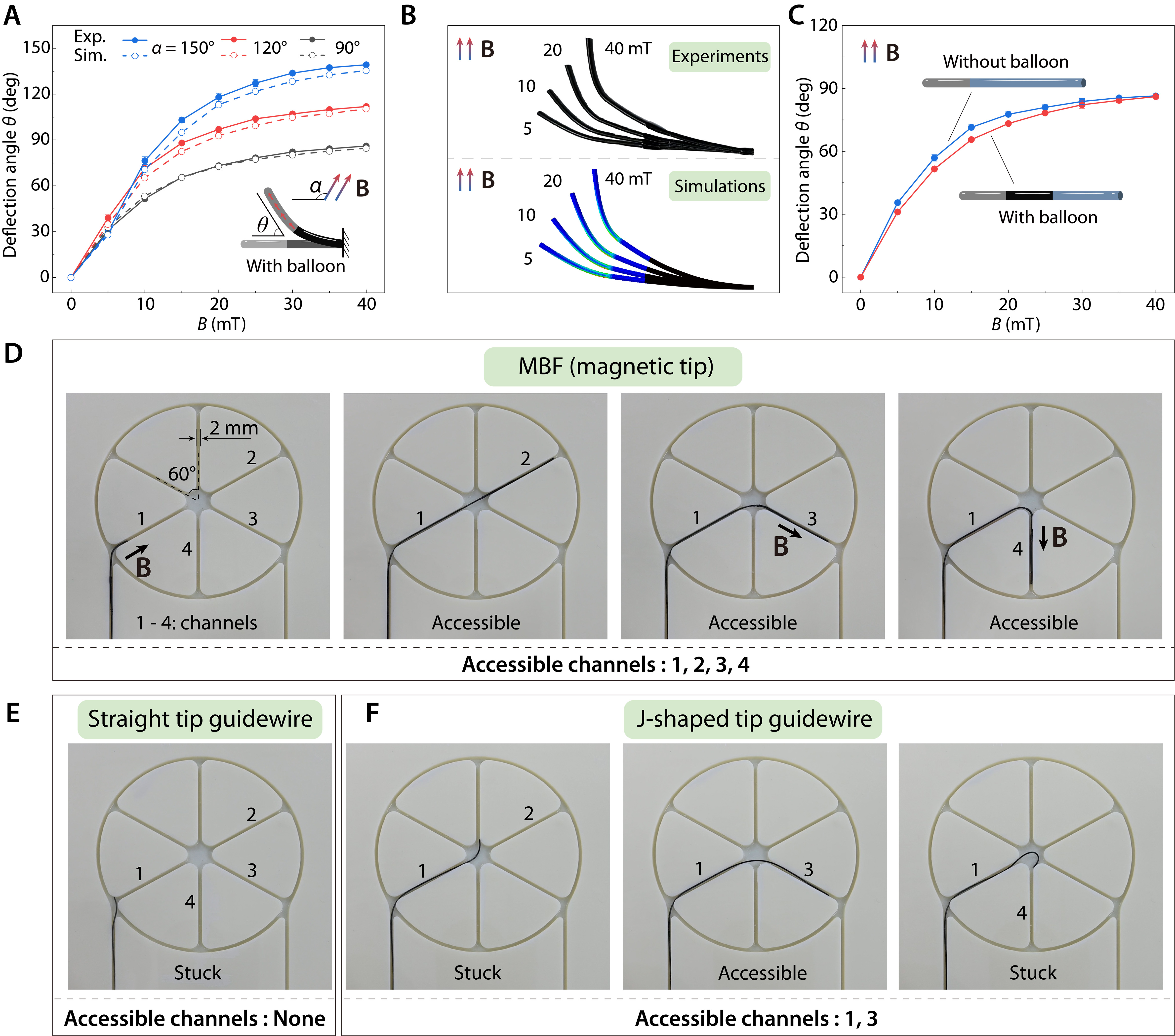
Figure 4. Magnetic deflection and navigation performance of the MBF. (A) Experimental and finite element simulation results of the deflection angle θ of the MBF with different field strength B and angle α; (B) Comparison of experiments and simulations at magnetic field angle α = 90°; (C) Comparison of the deflection angle of the MBF with and without the phase-change balloon, demonstrating the minimal impact of the balloon on navigation performance; (D) Accessibility test of the MBF in planar channels, showing successful navigation through all four channels under external magnetic fields; (E) Accessibility test of the commercial guidewire with a straight tip in planar channels, showing no accessibility to all channels; (F) Accessibility test of the commercial guidewire with J-shaped tip in planar channels, showing partial accessibility to only channels 1 and 3. For quantitative experimental data, error bars represent the standard deviation (SD), with n = 3 independent replicates. MBF: Magnetic balloon fiberbot; Exp.: experiment; Sim.: simulation.
To assess the MBF’s ability to navigate through complex branches of small arteries, we conducted accessibility tests in a planar model with four 2-mm-wide channels (labeled as channels 1, 2, 3, 4). As illustrated in Figure 4D, the MBF successfully accessed all four channels under the guidance of an external magnetic field, demonstrating its ability to navigate complex and narrow pathways. To further quantify this navigation performance, we conducted 10 repeated trials for representative branching paths and summarized the operation time, success rate in Supplementary Figure 12. In stark contrast, commercial guidewires with a straight tip [Figure 4E] or a J-shaped tip [Figure 4F] exhibited limited accessibility. The straight tip guidewire was stuck at the entrance and unable to navigate through any channels, while the J-shaped tip guidewire showed partial accessibility to channels 1 and 3 but failed to navigate to channels 2 and 4. These results underscore the MBF’s superior navigation capabilities compared to conventional guidewires, particularly in environments with narrow and tortuous pathways, as detailed in Supplementary Video 2.
Magnetic navigation and angioplasty demonstration of the MBF
To comprehensively evaluate the magnetic navigation performance of the MBF, we conducted a demonstration using a 3D-printed cerebrovascular phantom that replicates the intricate human cerebral arteries [Supplementary Figure 13], including the Circle of Willis (CW), the right internal carotid artery (ICA), and the right middle cerebral artery (MCA). Guided by external magnetic fields, the MBF successfully navigated through complex and tortuous branches. The navigation sequence, shown in Figure 5A, highlights the MBF’s ability to access small and narrow arterial branches. At 00:09, the MBF passed the curved ICA with a diameter of 3 mm. At 00:22, it successfully entered CW. Remarkably, at 00:38, the MBF navigated through an extremely narrow segment with a diameter of 1.6 mm. After that, MBF reached the M2 segment of the MCA at 00:47. The MBF continued to navigate seamlessly into even smaller arteries of MCA thereafter. The time-sequenced images and Supplementary Video 3 highlight the MBF’s smooth and consistent movement, even in highly curved and confined segments of the phantom. This demonstration underscores the MBF’s excellent navigation capabilities in small and tortuous blood vessels effectively, offering a promising solution for angioplasty in small arteries.
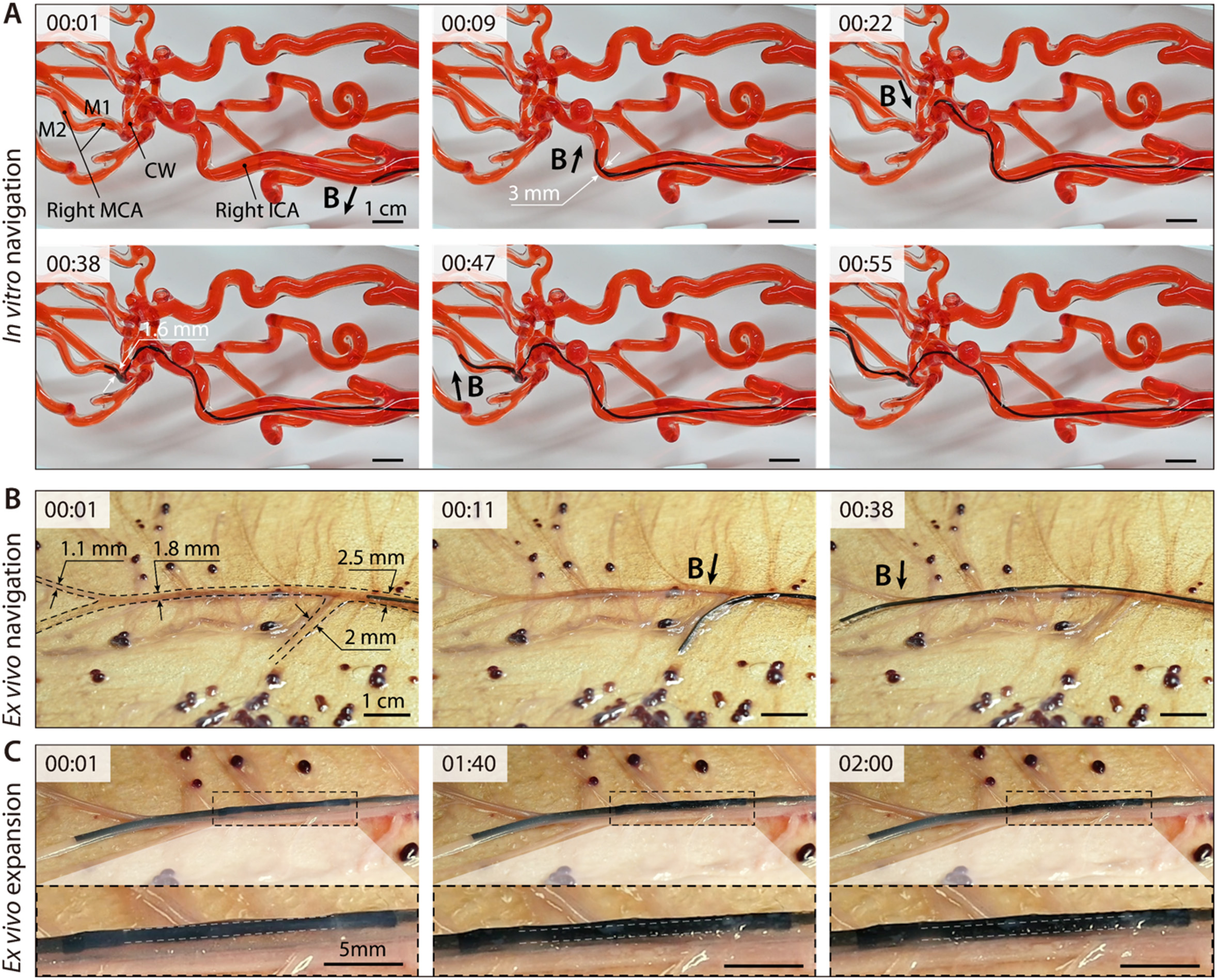
Figure 5. Magnetic navigation and angioplasty demonstration of the MBF. (A) The MBF successfully navigates complex and tortuous cerebral arteries such as the Circle of Willis (CW), right internal carotid artery (ICA), and right middle cerebral artery (MCA) in a 3D cerebrovascular phantom; (B) Magnetic navigation of the MBF in an ex vivo porcine placenta; (C) Phase-change expansion of the MBF via microwave heating. MBF: Magnetic balloon fiberbot; 3D: three-dimensional.
Following the demonstration of the MBF’s magnetic navigation capabilities in a 3D cerebrovascular phantom, we further performed biocompatibility testing and an ex vivo angioplasty demonstration in a porcine placenta model to assess its feasibility in a biologically relevant vascular environment. Cytotoxicity tests using L-929 fibroblast cells exposed to the MBF’s 100% sample extract, as well as diluted concentrations (25%, 50%, and 75%) are first performed. As shown in Supplementary Figure 14, the cells maintained over 90% viability across all extract concentrations, with no obvious differences compared to the negative control group. In contrast, the positive control group exhibited substantial cell damage, confirming the cytotoxicity of harmful substances. These results demonstrate that the MBF possesses excellent biocompatibility, making it suitable for vascular systems.
To validate the MBF’s angioplasty capability in a biologically relevant environment, we utilized a porcine placenta model for ex vivo testing. The porcine placenta is well-recognized for its vascular anatomy, which closely resembles the small arteries of the human brain, making it an ideal model for such demonstrations[55]. At 00:08, the MBF was steered by a repulsive magnetic field, achieving a 75° counterclockwise deflection to enter a 2 mm diameter vessel branch. After withdrawing from this branch at 00:31, the MBF was directed by an attractive magnetic field, producing a 15° clockwise deflection into a narrower branch with a diameter of 1.1 mm. Upon withdrawal from this branch at 00:38, the MBF was repulsed again, with a 15° counterclockwise deflection, successfully entering a 1.8 mm diameter vessel branch [Figure 5B and Supplementary Video 4]. Finally, the MBF’s phase-change balloon was activated via microwave heating to perform angioplasty within the porcine placenta’s vessels. As shown in Figure 5C and Supplementary Video 5, the balloon expanded radially and widened the vascular lumen, demonstrating the feasibility of microwave-triggered balloon expansion in small and tortuous vascular pathways.
DISCUSSION
This study presents a MBF for catheter-free angioplasty in small and tortuous arteries by integrating a magnetically deflectable tip with a phase-change balloon in a single platform. The current results from in vitro evaluation using a 3D cerebrovascular phantom, ex vivo validation in porcine placenta models, and biocompatibility tests support the feasibility of this design in the present study. By combining vascular navigation and balloon expansion within one device, the MBF provides a potential approach to address the limited navigation and delivery capability of conventional guidewire-catheter systems in narrow and complex vascular pathways.
At the same time, the present study is based on in vitro and ex vivo validation, whereas in vivo environments involve additional physiological factors such as blood flow, pulsatile pressure, vascular compliance, and dynamic device-tissue interactions. These factors will be important considerations in the next stage of evaluation. For the microwave-heating mechanism, although an empirical resonance-related optimum of the nitinol core was identified in the current setup, its behavior under more realistic tissue-loaded and physiological dielectric conditions still requires further investigation. Future work will therefore extend the evaluation to flow-enabled and pulsatile vascular platforms, followed by in vivo studies, to further assess thermal safety, including tissue viability, vascular-wall injury, local fluid temperature, and coagulation-related responses, as well as navigation stability and angioplasty performance under physiological conditions. More detailed electromagnetic characterization, including SAR-related analysis, will also be pursued to better quantify microwave energy deposition. In this process, additional safety-oriented control strategies, such as real-time temperature monitoring and automatic microwave shutoff near the upper limit of the actuation window, will also be explored to further reduce the risk of overheating. In parallel, the present sealed phase-change design and passive-cooling-based deflation mechanism can be further improved by enhancing balloon integrity, minimizing leakage risk, and integrating active deflation strategies - such as pressure-triggered microchannels - to improve procedural efficiency. The integration of real-time imaging and advanced electromagnetic navigation may also further enhance device controllability and treatment guidance[56,57].
CONCLUSIONS
In summary, we developed a MBF to facilitate catheter-free angioplasty within narrow and complex vascular pathways. Experimental evaluations demonstrated that the device can be magnetically steered to access highly tortuous branches as small as 1.1 mm. Furthermore, the MBF achieved controlled, wireless balloon expansion via low-power microwave heating, while exhibiting favorable biocompatibility and functional viability in ex vivo tests. These results demonstrate the feasibility of integrating magnetic navigation and microwave-triggered balloon actuation into a single platform for small-vessel intervention. Further research will focus on evaluating the system under more physiologically relevant conditions, and conducting in vivo studies to further assess its translational potential.
DECLARATIONS
Authors’ contributions
Conceptualization: Wang, L.; Chen, H.; Sun, Y.
Methodology: Wang, L.; Chen, H.; Sun, Y.; Peng, H.; Zhang, N.; Li, J.; Sui, M.; Cai, C.
Formal analysis: Chen, H.; Sun, Y.
Visualization: Wang, L.; Chen, H.; Lin, Y.
Funding acquisition, supervision: Wang, L.
Writing - original draft: Chen, H.; Lin, Y.; Peng, H.; Li, R.; Ye, S.
Writing - review and editing: Wang, L.; Chen, H.
Availability of data and materials
The authors declare that the primary data supporting the findings of this study are available within the paper and its Supplementary Materials. Additional data are available from the corresponding authors upon reasonable request.
AI and AI-assisted tools statement
During the preparation of this manuscript, the AI tool ChatGPT (version 5.4, released 2026-03-05) was used solely for language editing. The tool did not influence the study design, data collection, analysis, interpretation, or the scientific content of the work. All authors take full responsibility for the accuracy, integrity, and final content of the manuscript.
Financial support and sponsorship
This work was supported by the National Key Research and Development Program of China (Grant No. 2024YFE0215200), and the National Natural Science Foundation of China (Grant Nos. 12388101, 12532008, 12272369, 125B2045, 125B1010). Wang, L. acknowledges the support from Opening Fund of State Key Laboratory of Structural Analysis, Optimization and CAE Software for Industrial Equipment (Grant No. GZ24105), and the Fundamental Research Funds for the Central Universities (Grant No. YD2090002019). Chen, H. and Peng, H. acknowledge the support from Students’ Innovation and Entrepreneurship Foundation of USTC (Grant Nos. SC5290005507, SC5290005497).
Conflicts of interest
The authors declare that Chen, H., Sun, Y., and Wang, L. are inventors on a granted patent (Patent No. ZL202510369651.6) related to the work described in this paper. The other authors declare that there are no conflicts of interest.
Ethical approval and consent to participate
The ex vivo porcine placenta tissue used in this study was commercially obtained (Taobao, China) as an agricultural byproduct. This work did not involve live animals, animal handling, or animal euthanasia performed by the authors specifically for research purposes. The L-929 cell line used in this study is a commercially available established cell line; therefore, no ethical approval was required.
Consent for publication
Not applicable.
Copyright
© The Author(s) 2026.
Supplementary Materials
REFERENCES
1. Martin, S. S.; Aday, A. W.; Almarzooq, Z. I.; et al. ; on behalf of the American Heart Association Council on Epidemiology and Prevention Statistics Committee and Stroke Statistics Subcommittee. 2024 heart disease and stroke statistics: a report of US and global data from the American Heart Association. Circulation 2024, 149.
2. Feigin, V. L.; Abate, M. D.; Abate, Y. H.; et al. Global, regional, and national burden of stroke and its risk factors, 1990-2021: a systematic analysis for the Global Burden of Disease Study 2021. Lancet. Neurol. 2024, 23, 973-1003.
3. Ali, I., Arslan, B., Beasley, R., et al. Arterial revascularization. In Limb Preservation for the Vascular Specialist; Madassery, S., Patel, A., Eds.; Springer International Publishing, 2023; pp 77-249.
4. Li, J.; Chen, H.; Wang, L. Model-guided navigation of magnetic soft guidewire for safe endovascular surgery. J. Mech. Phys. Solids. 2024, 190, 105731.
5. Cannistraro, R. J.; Badi, M.; Eidelman, B. H.; Dickson, D. W.; Middlebrooks, E. H.; Meschia, J. F. CNS small vessel disease: a clinical review. Neurology 2019, 92, 1146-56.
6. Nelson, B. J.; Gervasoni, S.; Chiu, P. W. Y.; Zhang, L.; Zemmar, A. Magnetically actuated medical robots: an in vivo perspective. Proc. IEEE. 2022, 110, 1028-37.
8. Hwang, J.; Kim, J.; Choi, H. A review of magnetic actuation systems and magnetically actuated guidewire- and catheter-based microrobots for vascular interventions. Intel. Serv. Robot. 2020, 13, 1-14.
9. Yang, Z.; Zhang, L. Magnetic actuation systems for miniature robots: a review. Adv. Intell. Syst. 2020, 2, 2000082.
10. Chathuranga, D.; Lloyd, P.; Chandler, J. H.; Harris, R. A.; Valdastri, P. Assisted magnetic soft continuum robot navigation via rotating magnetic fields. IEEE. Robot. Autom. Lett. 2024, 9, 183-90.
11. Fischer, C.; Boehler, Q.; Nelson, B. J. Using magnetic fields to navigate and simultaneously localize catheters in endoluminal environments. IEEE. Robot. Autom. Lett. 2022, 7, 7217-23.
12. Dreyfus, R.; Boehler, Q.; Lyttle, S.; et al. Dexterous helical magnetic robot for improved endovascular access. Sci. Robot. 2024, 9, eadh0298.
13. Jeon, S.; Hoshiar, A. K.; Kim, K.; et al. A Magnetically Controlled Soft Microrobot Steering a Guidewire in a Three-Dimensional Phantom Vascular Network. Soft. Rob. 2019, 6, 54-68.
14. Wang, L.; Zheng, D.; Harker, P.; Patel, A. B.; Guo, C. F.; Zhao, X. Evolutionary design of magnetic soft continuum robots. Proc. Natl. Acad. Sci. U.S.A. 2021, 118, e2021922118.
15. Kim, Y.; Genevriere, E.; Harker, P.; et al. Telerobotic neurovascular interventions with magnetic manipulation. Sci. Robot. 2022, 7, eabg9907.
16. Kim, Y.; Parada, G. A.; Liu, S.; Zhao, X. Ferromagnetic soft continuum robots. Sci. Robot. 2019, 4, eaax7329.
17. Tiryaki, M. E.; Elmacıoğlu, Y. G.; Sitti, M. Magnetic guidewire steering at ultrahigh magnetic fields. Sci. Adv. 2023, 9, eadg6438.
18. Alverne, F. J. A. M.; Lima, F. O.; Rocha, F. D. A.; et al. Unfavorable vascular anatomy during endovascular treatment of stroke: challenges and bailout strategies. J. Stroke. 2020, 22, 185-202.
19. Chi, Y.; Zhao, Y.; Hong, Y.; Li, Y.; Yin, J. A perspective on miniature soft robotics: actuation, fabrication, control, and applications. Adv. Intell. Syst. 2023, 6, 2300063.
20. Yin, S.; Yao, D. R.; Song, Y.; et al. Wearable and implantable soft robots. Chem. Rev. 2024, 124, 11585-636.
21. Wu, S.; Hu, W.; Ze, Q.; Sitti, M.; Zhao, R. Multifunctional magnetic soft composites: a review. Multifunct. Mater. 2020, 3, 042003.
22. Wang, T.; Wu, Y.; Yildiz, E.; Kanyas, S.; Sitti, M. Clinical translation of wireless soft robotic medical devices. Nat. Rev. Bioeng. 2024, 2, 470-85.
23. Mu, J.; Meng, Z.; Liu, X.; Guan, P.; Lian, H. Implantable nanofiber membranes with synergistic photothermal and autophagy inhibition effects for enhanced tumor therapy efficacy. Adv. Fiber. Mater. 2023, 5, 1810-25.
24. Ge, Q.; Chen, Z.; Cheng, J.; et al. 3D printing of highly stretchable hydrogel with diverse UV curable polymers. Sci. Adv. 2021, 7, eaba4261.
25. Abbasi, S. A.; Ahmed, A.; Noh, S.; et al. Autonomous 3D positional control of a magnetic microrobot using reinforcement learning. Nat. Mach. Intell. 2024, 6, 92-105.
26. Hao, B.; Wang, X.; Dong, Y.; et al. Focused ultrasound enables selective actuation and Newton-level force output of untethered soft robots. Nat. Commun. 2024, 15, 5197.
27. Mirvakili, S. M.; Sim, D.; Hunter, I. W.; Langer, R. Actuation of untethered pneumatic artificial muscles and soft robots using magnetically induced liquid-to-gas phase transitions. Sci. Robot. 2020, 5, eaaz4239.
28. Tang, Y.; Li, M.; Wang, T.; Dong, X.; Hu, W.; Sitti, M. Wireless miniature magnetic phase-change soft actuators. Adv. Mater. 2022, 34, 2204185.
29. Sheng, H.; Zhang, X.; Liang, J.; et al. Recent advances of energy solutions for implantable bioelectronics. Adv. Healthcare. Mater. 2021, 10, 2100199.
30. Bioengineering and Biophysical Aspects of Electromagnetic Fields, 4th ed.; Greenebaum, B., Barnes, F., Eds.; CRC Press, 2018.
31. Yu, K.; Liu, Y.; Leng, J. Shape memory polymer/CNT composites and their microwave induced shape memory behaviors. RSC. Adv. 2014, 4, 2961-8.
32. Wang, C.; Jiang, H.; Cao, X.; et al. Graphite wrapped FeNi3/Co with carbon nanotubes anchored on MgO@carbon fiber reinforcements via continuous fabrication for high-efficiency microwave attenuation. Adv. Fiber. Mater. 2024, 6, 1640-56.
33. Li, Y.; Wu, J.; Yang, P.; et al. Multi-degree-of-freedom robots powered and controlled by microwaves. Adv. Sci. 2022, 9, 2203305.
34. Wang, Y. C.; Wang, Y. Z.; Shu, J. C.; Cao, W. Q.; Li, C. S.; Cao, M. S. Graphene implanted shape memory polymers with dielectric gene dominated highly efficient microwave drive. Adv. Funct. Mater. 2023, 33, 2303560.
35. Ahmed, K.; Zaidi, S. F. Mati-ur-rehman; Rehman, R.; Kondo, T. Hyperthermia and protein homeostasis: cytoprotection and cell death. J. Therm. Biol. 2020, 91, 102615.
36. Dewhirst, M. W.; Viglianti, B. L.; Lora-michiels, M.; Hanson, M.; Hoopes, P. J. Basic principles of thermal dosimetry and thermal thresholds for tissue damage from hyperthermia. Int. J. Hyperthermia. 2009, 19, 267-94.
37. Zhao, S.; Zou, J.; Zhang, A.; Xu, L. X. A new RF heating strategy for thermal treatment of atherosclerosis. IEEE. Trans. Biomed. Eng. 2019, 66, 2663-70.
38. Yang, Y.; Shi, W.; Yang, B.; Xiong, T.; Li, Z. A.; Ren, H. Regrafting submillimeter-scale ferromagnetic soft continuums. Nat. Commun. 2025, 16, 7023.
39. Singh, S. P. Microwave applicators for hyperthermia treatment of cancer: an overview. In 2018 3rd International Conference on Microwave and Photonics (ICMAP), Dhanbad, India, February 9-11, 2018; IEEE, 2018, pp 1-3.
40. Giombini, A.; Giovannini, V.; Cesare, A. D.; et al. Hyperthermia induced by microwave diathermy in the management of muscle and tendon injuries. Br. Med. Bull. 2007, 83, 379-96.
41. Li, M.; Tang, Y.; Soon, R. H.; Dong, B.; Hu, W.; Sitti, M. Miniature coiled artificial muscle for wireless soft medical devices. Sci. Adv. 2022, 8, eabm5616.
42. Soon, R. H.; Yin, Z.; Dogan, M. A.; et al. Pangolin-inspired untethered magnetic robot for on-demand biomedical heating applications. Nat. Commun. 2023, 14, 3320.
43. Duan, M.; Zhu, X.; Fan, L.; et al. Phase-transitional bismuth-based metals enable rapid embolotherapy, hyperthermia, and biomedical imaging. Adv. Mater. 2022, 34, 2205002.
44. Sun, X.; Guo, R.; Yuan, B.; et al. Stiffness tunable implanted electrode enabled by magnetic liquid metal for wireless hyperthermia. Appl. Mater. Today. 2022, 27, 101495.
45. Jiang, J.; Fei, W.; Pu, M.; Wu, Z. Wireless liquid-alloy-based induction heating for soft devices by alternating magnetic field: from characterization to application. Sens. Actuat. A. Phys. 2022, 340, 113538.
46. Jung, W.; Lee, S.; Hwang, Y. Wireless inchworm-like compact soft robot by induction heating of magnetic composite. Micromachines 2023, 14, 162.
47. Hassani, F.; Nekoovaght, P. M.; Gharib, N. The influence of microwave irradiation on rocks for microwave-assisted underground excavation. J. Rock. Mech. Geotech. Eng. 2016, 8, 1-15.
48. Tang, L.; Wang, J.; Zhang, B.; Li, C.; Jin, H. Remarkable microwave heating performance of MWCNTs/polypropylene composites verified by electromagnetic-thermal coupling experiment and simulation. Compos. Sci. Technol. 2022, 223, 109428.
49. Li, Q.; Zhang, Z.; Qi, L.; Liao, Q.; Kang, Z.; Zhang, Y. Toward the application of high frequency electromagnetic wave absorption by carbon nanostructures. Adv. Sci. 2019, 6, 1801057.
50. Guo, Y.; Bai, Y.; Lu, Y. Flexible CNT-MXene-CNT film with low surface conductance for high- and low-power electromagnetic absorption protection. ACS. Appl. Electron. Mater. 2023, 5, 6859-73.
51. Zhao, C.; Kang, J.; Li, Y.; Wang, Y.; Tang, X.; Jiang, Z. Carbon-based stimuli-responsive nanomaterials: classification and application. Cyborg. Bionic. Syst. 2023, 4, 0022.
52. Wang, K.; Chu, W.; Liu, X.; Li, X.; Liu, H. Recent advances in carbon-based microwave-absorbing aerogel. Soft. Sci. 2026, 6.
53. Sunwoo, S.; Han, S. I.; Park, C. S.; et al. Soft bioelectronics for the management of cardiovascular diseases. Nat. Rev. Bioeng. 2023, 2, 8-24.
54. Ebrahimi, A.P. Mechanical properties of normal and diseased cerebrovascular system. J Vasc Interv Neurol 2009, 2, 155-162.
55. Wang, B.; Wang, Q.; Chan, K. F.; et al. tPA-anchored nanorobots for in vivo arterial recanalization at submillimeter-scale segments. Sci. Adv. 2024, 10, eadk8970.
56. Gervasoni, S.; Pedrini, N.; Rifai, T.; et al. A human-scale clinically ready electromagnetic navigation system for magnetically responsive biomaterials and medical devices. Adv. Mater. 2024, 36, 2310701.
Cite This Article
How to Cite
Download Citation
Export Citation File:
Type of Import
Tips on Downloading Citation
Citation Manager File Format
Type of Import
Direct Import: When the Direct Import option is selected (the default state), a dialogue box will give you the option to Save or Open the downloaded citation data. Choosing Open will either launch your citation manager or give you a choice of applications with which to use the metadata. The Save option saves the file locally for later use.
Indirect Import: When the Indirect Import option is selected, the metadata is displayed and may be copied and pasted as needed.
About This Article
Special Topic
Copyright

Data & Comments
Data
0


Comments
Comments must be written in English. Spam, offensive content, impersonation, and private information will not be permitted. If any comment is reported and identified as inappropriate content by OAE staff, the comment will be removed without notice. If you have any queries or need any help, please contact us at support@oaepublish.com.