


Microstructural evolution and fatigue mechanism of 316LN austenitic stainless steel welded joint at 4.2 K
 0
0 Abstract
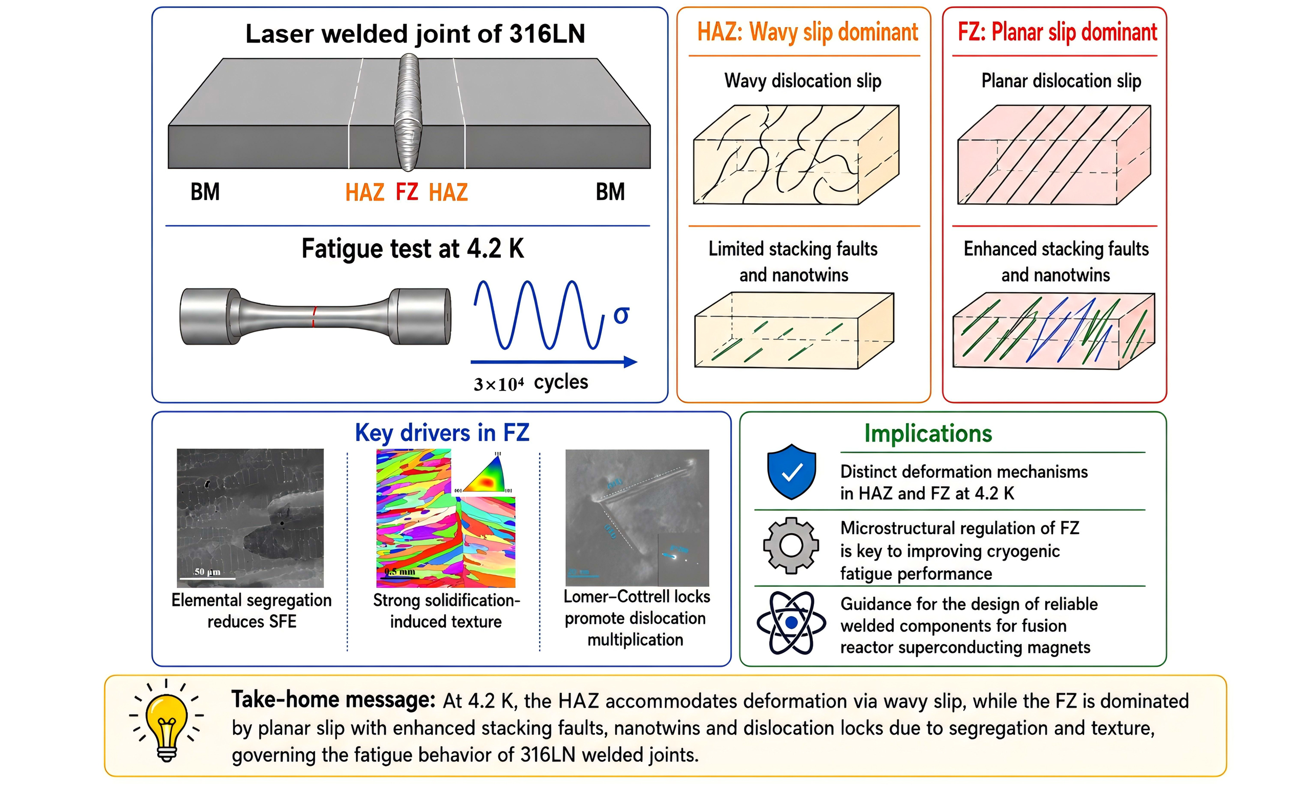
The large-scale superconducting magnets used in the International Thermonuclear Experimental Reactor (ITER), demand structural materials that can endure long-term cyclic electromagnetic loading at 4.2 K. In this study, the microstructural evolution and plasticity mechanisms of a 316LN stainless steel welded joint subjected to fatigue at 4.2 K were systematically investigated for the first time. A combination of nanoindentation, electron backscatter diffraction, energy dispersive spectroscopy, electron channeling contrast imaging and transmission electron microscopy was employed for comprehensive characterization. The results reveal distinct fatigue mechanisms between the heat-affected zone (HAZ) and the fusion zone (FZ). The HAZ primarily accommodates deformation through wavy dislocation slip, while the FZ is dominated by planar slip. Notably, the FZ exhibits enhanced formation of stacking faults and nanotwins. These features are attributed to the elemental segregation in the interdendritic regions, which locally reduces the stacking fault energy and lowers the critical stress required for stacking fault formation via dislocation dissociation. Besides, a strong solidification-induced texture is formed in the FZ, which increases the local Schmid factor and thereby the resolved shear stress for promoting the nucleation of stacking faults and nanotwins. Additionally, Lomer-Cottrell locks are observed in the FZ as a result of dominant planar slip, contributing to dislocation multiplication. These findings offer important insights into the cryogenic fatigue behavior of austenitic stainless steel welds and contribute to the design of reliable structural components for fusion energy applications.
Keywords
INTRODUCTION
316LN austenitic stainless steel is a critical structural material for superconducting magnetic confinement fusion reactors owing to its excellent combination of high strength, exceptional ductility, high fracture toughness and non-magnetic properties[1-4]. During operation at liquid helium temperature (4.2 K), electromagnetic loads generated during plasma disruptions impose cyclic stress on 316LN components, making them susceptible to fatigue damage. The acceptance criterion for the International Thermonuclear Experimental Reactor (ITER) correction coil cases requires a fatigue limit of at least 500 MPa after a minimum of 30,000 cycles[5]. These ITER correction coil cases are large welded structures of 316LN, with the welded joints being the most susceptible regions to fatigue damage. Thus, understanding the microstructural evolution and fatigue mechanisms of welded joints at 4.2 K is critical for ensuring the long-term reliability and structural integrity of these components under extreme service conditions.
At cryogenic temperatures, the plasticity mechanisms of austenitic stainless steels include dislocation slip, deformation twinning and martensitic transformation[6-8]. The reduced thermal activation at cryogenic temperatures increases the resistance to dislocation slip while promoting planar slip[9]. Nevertheless, dislocations remain mobile and continue to multiply during deformation, forming dislocation tangles or cells that generate high internal stresses to initiate microcracks[7,10,11]. Below a critical temperature, e.g., ~34 K for 316LN[12], the mobility of screw dislocations becomes lower than that of edge dislocations, leading to pronounced serrated plastic flow and the formation of localized deformation bands on the deformed specimens[13]. Deformation twinning is normally promoted under cryogenic conditions due to enhanced interactions between dislocations and stacking faults[7,9,10,14], which contributes to improved toughness and ductility[15]. Martensitic transformation is another critical deformation mechanism in austenitic stainless steels at cryogenic temperatures. As the temperature decreases, the critical stress required for strain-induced martensitic transformation is reduced, allowing the transformation to initiate earlier during deformation[16]. This transformation-induced plasticity (TRIP) effect enhances strain hardening, absorbs deformation energy, and delays the onset of necking and fracture[17,18]. Notably, stacking fault energy (SFE) plays a decisive role in governing these dominant deformation mechanisms[19]. In austenitic steels, an increase in SFE can shift the mechanism from martensite-driven TRIP to twinning-induced plasticity (TWIP)[20,21]. While the TRIP effect primarily enhances strength, the TWIP effect improves ductility, offering a favorable balance of mechanical properties for cryogenic applications[22].
At 4.2 K, both deformation twinning and martensitic deformation are normally activated during the deformation of 316LN stainless steels[23-26]. Under uniaxial tension at this temperature, martensitic transformation generally follows the γ → α’ pathway, which enhances strength and ductility but reduces fracture toughness[10,27-31]. Liu et al.[26] reported that ~43 vol.% of austenite transforms into α’-martensite when 316LN is deformed to fracture at 50% engineering strain. Nevertheless, detailed transmission electron microscopy (TEM) analyses by Xin et al.[15] revealed the presence of a small amount of ε-martensite, only a few nanometers thick, in 316LN after tensile deformation. Similarly, Singh et al.[32] found that the plasticity mechanism of 316L stainless steel at 15 K involves stacking fault formation, the two-step martensitic transformation (γ → ε → α’) and α’-martensite twinning, which collectively result in significantly improved fatigue life compared to room temperature. However, under high-cycle fatigue at 4.2 K, Xin et al.[7] observed that 316LN maintains highly stable magnetization under strong magnetic fields, indicating the absence of martensitic transformation. Consistently, Fu et al.[33] reported that only nanotwins were observed in 316LN welds after fracture toughness tests at 4.2 K. Conversely, other studies have shown the formation of dense nanometer-sized ε-martensite in 316LN welds after fracture toughness testing at 4.2 K[34]. These conflicting observations suggest that the plasticity mechanisms of 316LN welds under cyclic loading are complex and likely depend on the initial weld microstructure and loading conditions. Notably, the weld zone undergoes significant microstructural evolution due to localized melting and rapid solidification during welding[35]. This non-equilibrium solidification introduces a high density of crystal defects and elemental segregation[36], which may substantially alter the dominant deformation mechanisms during fatigue.
This study aims to explore the microstructural evolution and plasticity mechanisms of 316LN laser-welded joints subjected to fatigue at 4.2 K. Detailed microstructural characterization of the fusion zone (FZ), heat-affected zone (HAZ) and base material (BM) after cyclic loading was conducted using electron backscatter diffraction (EBSD), electron channeling contrast imaging (ECCI) and TEM. Based on the comprehensive observations, the plasticity mechanisms during cyclic loading were systematically analyzed. These findings provide valuable insights for optimizing the design, ensuring the safe operation and managing the aging of structural materials in nuclear fusion reactors under extreme cryogenic conditions.
EXPERIMENTAL
The BM used in this study is a hot-rolled 316LN austenitic stainless steel plate with the chemical composition (in wt.%): 0.02% C, 16.33% Cr, 12.53% Ni, 0.5% Si, 1.67% Mn, 2.1% Mo, 0.11% N, 0.015% P, 0.001% S,
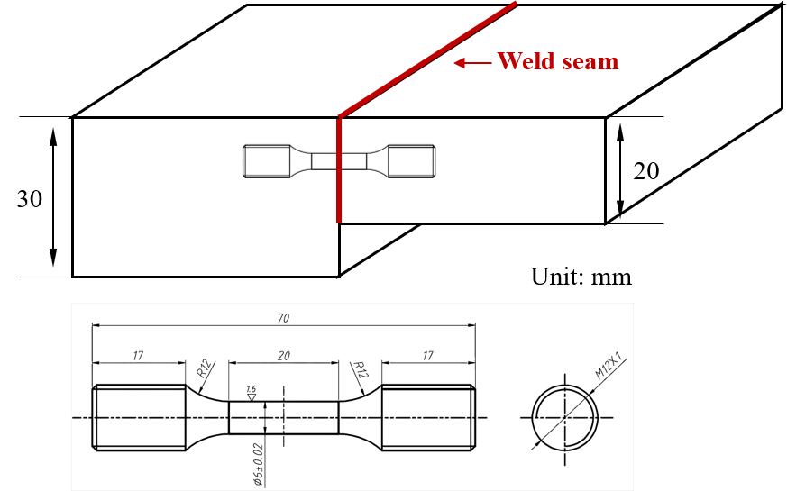
Figure 1. Schematic illustrating the sampling location, orientation, geometry and dimensions of the specimen for fatigue tests.
As shown in Figure 1, the fatigue specimens were machined from the welded plate with their loading axis oriented perpendicular to the weld seam. The gauge section has a length of 20 mm and a diameter of 6 mm. Fatigue tests were conducted at 4.2 K according to the JIS Z2283 standard. The specimens were subjected to cyclic loading between 85 and 850 MPa for 30,000 cycles at 1 Hz using a sinusoidal waveform. Noted that the yield stress of BM measured by uniaxial tensile tests is ~822 MPa at 4.2 K[34]. The fatigue test of the specimen was stopped at 30,100 cycles without fracture, and after testing, specimens were sectioned parallel to the loading direction by wire-electrode cutting for microstructural analysis. This study focuses on the microstructural evolution of the HAZ and FZ.
EBSD, ECCI and energy dispersive spectroscopy (EDS) were performed using a ThermoFisher Verios 5UC scanning electron microscope equipped with an Oxford C Swift device. The accelerating voltages were 15 kV for EBSD, and 20 kV for ECCI as well as EDS. The step size for EBSD mapping is 1.2 μm. The EBSD maps of the initial microstructure are provided in Supplementary Figure 1, while the corresponding post-fatigue maps are shown in Figure 2. In addition, key microstructural parameters, including grain size, geometrically necessary dislocation density and Schmid factor, for both conditions are summarized in Table 1 for direct comparison. Nanoindentation testing was carried out using a FemtoTool system equipped with a Berkovich tip. Indentations were performed at a constant displacement rate of 0.5 μm/s, reaching a maximum depth of 500 nm. A total of 400 × 150 indents were made with 5 μm spacing, covering an area of 2,000 × 750 μm2 under consistent loading conditions. TEM samples were extracted from fatigue specimens and thinned to electron transparency using focused ion beam milling (ThermoFisher Helios 5UX). High-resolution TEM (HRTEM, ThermoFisher Talos F200X) and aberration-corrected scanning TEM (STEM, JEOL JEM-ARM300F2) were employed to analyze the microstructures in detail.
Figure 2. (A) Phases map, (B) Schmid factor map, (C-C3) inverse pole figures, (C4-C6) grain size statistical diagrams, (D) Kernel average misorientation map, and (D1-D3) GND density statistical diagrams of the as-fatigued welded joint. BM: Base material; HAZ: heat-affected zone; FZ: fusion zone; GND: geometrically-necessary dislocation; FCC: face-centered cubic; BCC: body-centered cubic.
EBSD data of welded joint before and after fatigue testing at 4.2 K
| Region | HAZ | FZ | |
| Grain size (μm) | Initial | 24.69 | 79.33 |
| As-fatigued | 30.01 | 75.51 | |
| GND density (m-2) | Initial | 3.02 × 10¹³ | 1.86 × 10¹³ |
| As-fatigued | 3.26 × 10¹³ | 2.56 × 10¹³ | |
| Schmid factor | Initial | 0.46 | 0.43 |
| As-fatigued | 0.44 | 0.47 | |
RESULTS
As illustrated in Figure 2, the microstructure of the 316LN welded joint is divided into three distinct regions: BM, HAZ and FZ. Crucially, no voids were observed within the weld region, a key factor conducive to enhanced fatigue life[37]. Figure 2A confirms that the 316LN retains a single-phase austenitic structure after both welding and cyclic loading, demonstrating excellent austenite stability under cryogenic fatigue conditions. The inverse pole figures (IPFs) in Figure 2C-C3 provide a detailed view of the grain morphology and crystallographic orientation across the joint. The BM exhibits fine equiaxed grains with a weak texture. In contrast, the FZ consists of coarse columnar grains that grew opposite to the thermal gradient during solidification, which exhibits a significantly-enhanced texture. The average grain sizes of HAZ and FZ are 30.01 μm and 75.51 μm, respectively, as shown in Figure 2C5-C6 and summarized in Table 1. The slight differences in the average grain sizes before and after cyclic loading are attributed to variations in measurement that arise from the small mapping area relative to the large grain size. The Schmid factor map for the {111}<110> slip system, relative to the loading direction perpendicular to the fusion line, is shown in Figure 2B, with the corresponding average values provided in Table 1. Similar to grain size, the observed variations in Schmid factors of HAZ and FZ before and after cyclic loading are likely due to measurement uncertainty rather than microstructural changes.
Figure 2D is the Kernel average misorientation map, showing the distribution of geometrically-necessary dislocations (GNDs) in different regions. The GND density (ρGND) was calculated using[38]:
where Δθi is the weighted average of local misorientation, μ is the scanning step size (1.2 μm) and b is the Burgers vector of the current 316LN stainless steel (0.254 nm)[38]. Figure 2D1-D3 display the frequency distributions of GND densities in BM, HAZ and FZ. Table 1 lists the average GND densities for samples before and after cyclic loading. HAZ exhibits a GND density higher than that of FZ. Yet, the increment in GND density after cyclic loading is larger in FZ (37.63%) compared to HAZ (7.95%). This suggests that the higher GND density in HAZ is attributed to the welding process, and FZ experiences more plasticity during cyclic loading.
To further exam the microstructure evolution of the welded joint after cyclic loading, the local mechanical properties were measured using nanoindentation. Figure 3A presents the hardness map across the three distinct regions of the welded joint after cyclic loading. Since measurements were taken within individual grains, the hardness values primarily reflect the defect density inside the grains, independent of grain boundary effects. To illustrate the hardness variation across the three regions, the hardness values were averaged along the Y-axis and plotted as a function of the X position [Figure 3B]. The results reveal that BM exhibits the highest hardness, which decreases significantly in FZ. Nevertheless, after normalizing the hardness by the grain orientation-dependent Taylor factor, the different regions display comparable normalized hardness values. This suggests that the observed hardness variations are mainly attributed to the difference in grain orientation rather than internal defect density. Furthermore, the comparable normalized hardness across all regions implies that, although plastic deformation is primarily concentrated in the FZ as revealed by the GND density measurement [Table 1], the difference is not large enough to produce a clear variation in hardness.
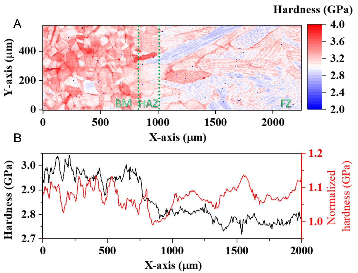
Figure 3. Hardness distribution across the three distinct regions after cyclic loading at 4.2 K: (A) hardness map; (B) average hardness and Taylor factor-normalized average hardness plotted as a function of the X position.
Electron channeling contrast imaging, with a high spatial resolution, enables direct observation of dislocations near the surface (~100 nm depth) and when combined with slip trace analysis, can identify active slip systems[39,40]. Thus, the microstructural evolution of the HAZ before and after cyclic loading at
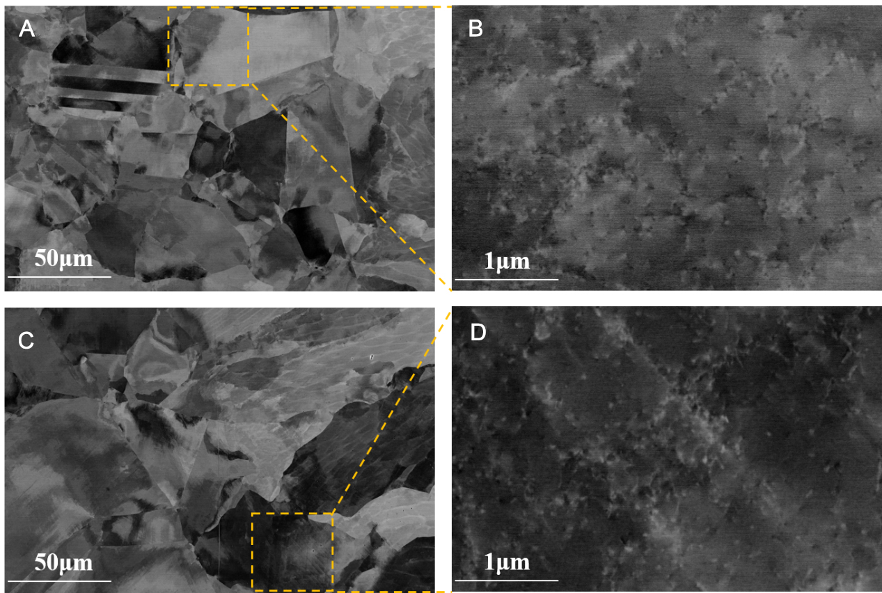
Figure 4. ECCI images of the HAZ before and after cyclic loading at 4.2 K: (A) HAZ before fatigue, (B) the magnified view of the region marked by the dash rectangle in (A), (C) HAZ after fatigue, (D) the magnified view of the region marked by the dash rectangle in (C). ECCI: Electron channeling contrast imaging; HAZ: heat-affected zone.
Figure 5A presents the ECCI image of the FZ prior to cyclic loading, revealing a distinct post-weld dendritic structure with an average dendrite size of ~80 μm. EDS analysis confirms the enrichment of Cr, Mn, and Mo in the interdendritic regions [Figure 5A1-A4], which is attributed to rapid cooling and non-equilibrium solidification in the FZ, as widely reported in the literature[41-43]. The results of EDS point measurements for dendritic and interdendritic regions are summarized in Table 2. Interdendritic elemental segregation in laser welds primarily arises from the significant deviation of solidification from equilibrium. The extremely high cooling rate during welding leads to a solidification rate so rapid that solid-phase diffusion is effectively suppressed, preventing compositional homogenization. Meanwhile, liquid-phase diffusion and convective mixing cannot keep pace with the advancing solidification front, resulting in the concentrated accumulation of solutes in confined interdendritic spaces.
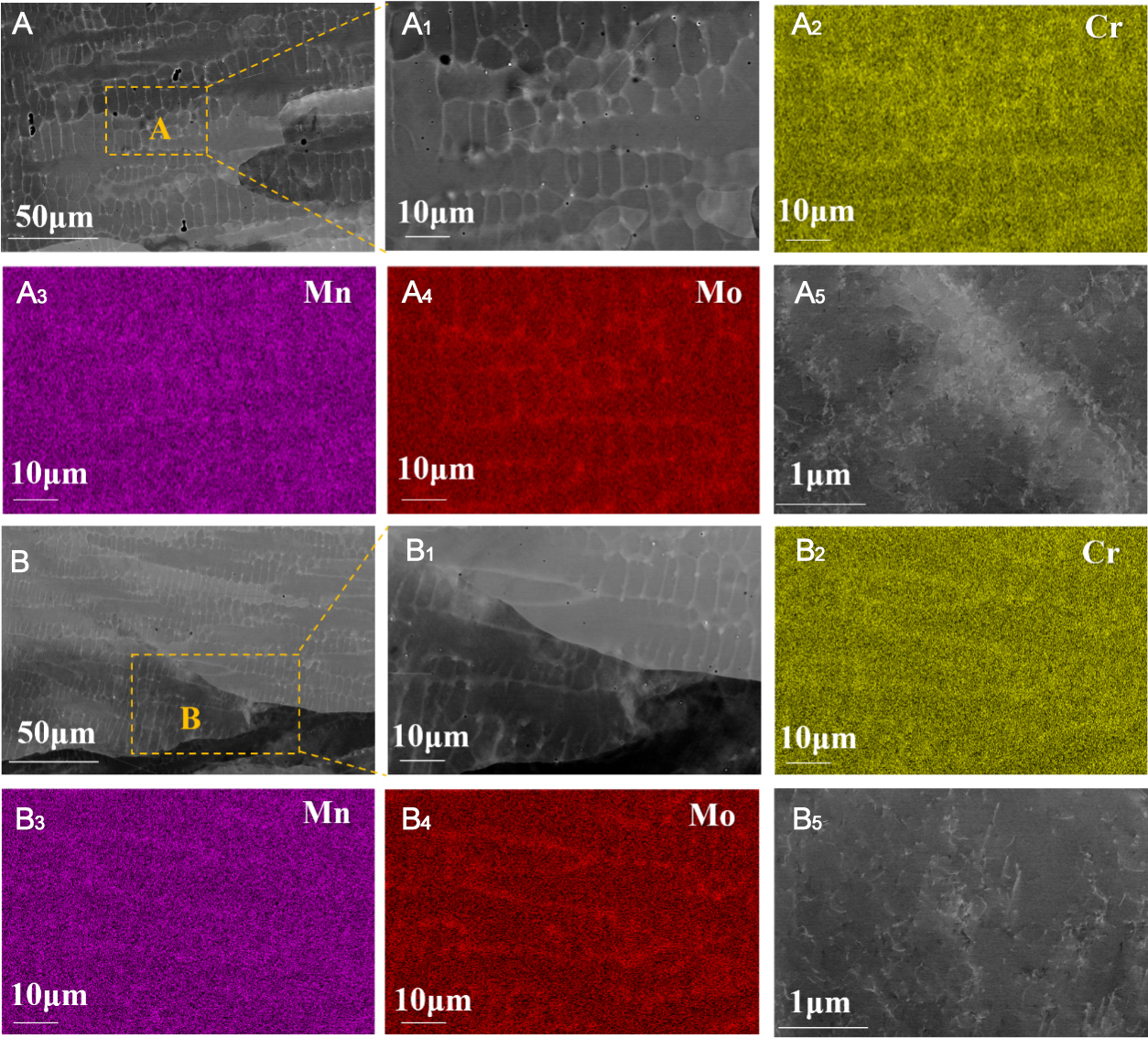
Figure 5. ECCI images and EDS maps of the FZ before and after cyclic loading at 4.2 K: (A) FZ before fatigue, (A1) the magnified image in dash rectangle in (A), (A2) to (A4) the EDS elemental distribution maps corresponding to (A1), (A5) the magnified image in dash rectangle in (A) showing the dislocations, (B) FZ after fatigue, (B1) the magnified image in yellow rectangle in (B), (B2) to (B4) the EDS elemental distribution maps corresponding to (B1), (B5) the magnified image in dash rectangle in (B) showing the dislocations. EDS: Energy dispersive spectroscopy; ECCI: electron channeling contrast imaging; FZ: fusion zone.
The chemical compositions of the dendrite and interdendrite in FZ after cyclic loading
| Position | Point | Ni | Cr | Mn | Si | Mo |
| Interdendrite | #1 | 13.7 | 18.8 | 2.1 | 0.7 | 3.3 |
| #2 | 13.6 | 19.4 | 2.2 | 0.9 | 4.3 | |
| #3 | 13.7 | 18.4 | 2.0 | 0.7 | 3.0 | |
| #4 | 13.9 | 18.8 | 2.2 | 0.8 | 3.4 | |
| Dendrite | #1 | 12.7 | 16.2 | 1.4 | 0.5 | 1.6 |
| #2 | 12.6 | 16.1 | 1.4 | 0.4 | 1.4 | |
| #3 | 12.7 | 16.3 | 1.5 | 0.4 | 1.5 | |
| #4 | 12.7 | 16.4 | 1.5 | 0.5 | 1.6 |
Similar to the HAZ, a relatively high density of dislocations is already present in the FZ before fatigue [Figure 5A5], introduced by residual stresses and localized deformation during welding. Additionally, the rapid solidification associated with laser welding is known to generate dislocations and dislocation cells, with densities far exceeding those caused by constitutional stresses from microsegregation during directional solidification[44,45]. After fatigue, the FZ retains a well-defined dendritic structure [Figure 5B] and pronounced elemental segregation at interdendritic regions [Figure 5B1-B4], indicating that the plastic strain induced by fatigue was not severe. Otherwise, intense shear deformation on multiple slip systems would have disrupted the segregation. Moreover, the dislocation density in the FZ increases markedly after fatigue [Figure 5B5], consistent with the GND measurements shown in Table 1. Careful examination of larger regions revealed no evidence of ε-martensite or deformation twins, consistent with the observations in the HAZ.
Plastic deformation in metallic materials primarily occurs through slip activities accompanied by dislocation gliding which is of great interest for understanding, predicting and enhancing the mechanical behavior of materials. To investigate the slip behavior of the 316LN welded joint after fatigue, EBSD mapping was conducted on grains exhibiting slip traces in both HAZ and FZ. By correlating the slip trace orientations with the crystallographic orientations of the grains, it was determined that plasticity deformation in 316LN is predominantly governed by the {111}<110> slip system with large Schmid factors, as shown in Figure 6A-B2. In the HAZ, two sets of slip bands intersecting at approximately 45° were observed within individual grains [Figure 6A1]. This configuration explicitly indicates the activation of multiple slip systems and the occurrence of cross-slip. Moreover, cross slip of dislocation plays an important role in work hardening[46], resulting in a high hardness in HAZ as shown in Figure 3.
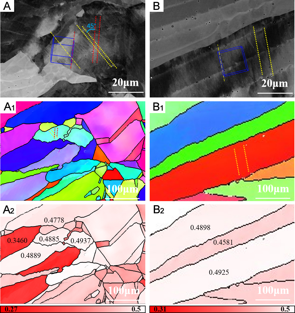
Figure 6. ECCI and EBSD images of the HAZ and FZ after cyclic loading at 4.2 K: (A) ECCI image, (A1) IPF and (A2) Schmid factor image of HAZ, (B) ECCI image, (B1) IPF and (B2) Schmid factor image of FZ. ECCI: Electron channeling contrast imaging; EBSD: electron backscatter diffraction; HAZ: heat-affected zone; FZ: fusion zone; IPF: inverse pole figure.
In contrast, the larger grains in the FZ primarily exhibited single-direction slip bands, suggesting the dominance of a planar slip mode [Figure 6B and B1]. Non-equilibrium segregation of solute elements (such as Ni, Cr, Mo, Mn) in the weld is expected to form local low SFE zones [Figure 5 and Table 2]. Shao et al.[47] revealed that reducing the Mn content within Fe-xMn-0.6C alloys leads to a significant decrease in SFE, consequently driving a transition of dislocation slip mode from wavy slip to planar slip. For low SFE in FZ, perfect dislocations readily dissociate into Shockley partial dislocation pairs. Partial dislocations cannot cross-slip unless they recombine into a perfect dislocation. Therefore, it is generally accepted that cross-slip of partial dislocation is very difficult[48,49]. Overall, cross-slip is more easily activated in the HAZ, while a planar slip mode prevails in the FZ. As illustrated in Figure 6A2 and B2, the slip bands align with regions of consistently high Schmid factors, which own to the critical shear stress for the initiation of slip system is directly proportional to the Schmid factor. A high Schmid factor indicates that the resolved shear stress is more likely to reach the critical resolved shear stress, thereby promoting slip activation.
To further clarify the plasticity mechanisms of the 316LN welded joint during cyclic loading, TEM characterization was performed on the HAZ. Figure 7A shows a typical bright-field TEM image of the HAZ before cyclic loading, revealing a relatively high dislocation density with sparse dislocation tangles localized near prior austenite grain boundaries, consistent with the ECCI observations in Figure 4B. The corresponding selected area electron diffraction (SAED) pattern [Figure 7B] displays only diffraction spots from the austenitic matrix. A HRTEM image [Figure 7C] further confirms the absence of deformation twins or martensite. After cyclic loading, the HAZ exhibits a comparable dislocation density to that of the initial condition, as shown in Figure 7D, but with dislocations forming more pronounced tangles. A long dislocation pile-up is also observed, consistent with the slip bands shown in the ECCI image [Figure 4D]. Detailed examination of multiple regions reveals the formation of stacking faults within the grain interiors, which do not connect to grain boundaries, as shown in Figure 7E. High-angle annular dark-field (HAADF) STEM imaging was further used to identify nanotwins and stacking faults. As shown in Figure 7F, isolated stacking faults are clearly observed within the grain interiors of the HAZ after fatigue. These stacking faults result from the dissociation of perfect dislocations into Shockley partial dislocation pairs. Careful inspection of multiple locations confirms that neither deformation twins nor martensite formed in the HAZ during cyclic loading.
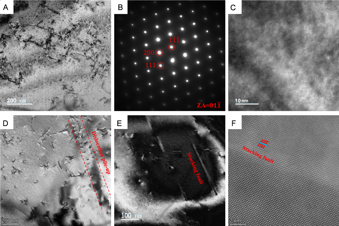
Figure 7. TEM images of the HAZ before and after cyclic loading at 4.2 K: (A) the bright-field image before fatigue, (B) the SAED pattern obtained from (A), (C) the HRTEM image obtained from (A), (D) the bright-field image after fatigue, (E) the image of HAZ after fatigue showing the formation of stacking faults, (F) HAADF STEM imaging of HAZ after fatigue, showing the stacking faults. TEM: Transmission electron microscopy; HAZ: heat-affected zone; SAED: selected area electron diffraction; HRTEM: high-resolution TEM; STEM: scanning TEM; HAADF: high-angle annular dark-field.
Figure 8A displays an aberration-corrected STEM image of the FZ before fatigue, revealing a relatively low dislocation density, consistent with the ECCI observation in Figure 5A1. The SAED pattern confirms that the FZ consists solely of an austenitic phase, without deformation twins, or martensite [Figure 8B]. After cyclic loading at 4.2 K, a significant increase in dislocation density is observed in the FZ [Figure 8C], forming the dislocation tangle structure. The weak-beam dark-field images reveal dissociated dislocations and the formation of Lomer-Cottrell locks [Figure 8D-F]. During the initial stages of fatigue, the motion of leading partial dislocations is followed by trailing partials that eliminate the intervening stacking faults. The interaction between two leading partial dislocations in conjugate {111} planes results in the formation of a Lomer-Cottrell lock. For example, as shown in Figure 8E, two perfect dislocations with respective Burgers vectors of
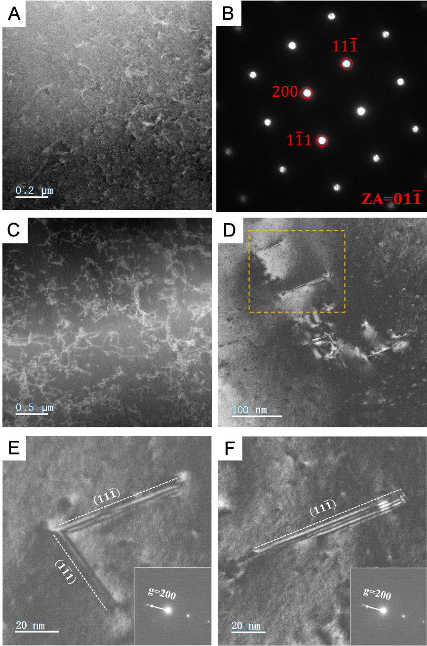
Figure 8. TEM images of the FZ before and after cyclic loading at 4.2 K: (A) the STEM image of the FZ before fatigue, showing the dislocations, (B) the SAED pattern obtained from (A), (C) the STEM image of the FZ after fatigue, showing the dislocation multiplication, (D) The weak-beam dark-field images of dislocations in the FZ after fatigue, (E) the image of a Lomer-Cottrell lock that formed by the reaction of two partial dislocations in the FZ after fatigue, (F) the images of dissociated dislocations in the FZ after fatigue. TEM: Transmission electron microscopy; FZ: fusion zone; STEM: scanning transmission electron microscopy; SAED: selected area electron diffraction.
The interaction of the leading partials produces a stair-rod dislocation,
This
HAADF-STEM was used to investigate the atomic-scale microstructure of the FZ before and after fatigue. As shown in Figure 9A, dislocations are already present in the FZ prior to fatigue, and the inverse fast Fourier transform (FFT) of the SAED pattern confirms their presence [Figure 9B]. After fatigue deformation, numerous nanotwins are observed in the FZ, with sizes ranging from 4.50 nm to 8.24 nm in length and only a few atomic layers in thickness, as illustrated in Figure 9C. These observations indicate that fatigue deformation in the FZ is accommodated by multiple concurrent mechanisms, including dislocation slip, stacking fault formation and deformation-induced nano-twinning. The atomic structure of the nanotwins is clearly resolved in the HAADF-STEM image in Figure 9D, where their nucleation and growth are found to originate from the bases of stacking faults. Notably, localized chemical composition segregation is observed along stacking faults and nanotwins, which promotes the formation of a high density of stacking faults that act as preferential nucleation sites for nanotwins. In contrast, no deformation twins are detected in the HAZ after cyclic loading at 4.2 K.
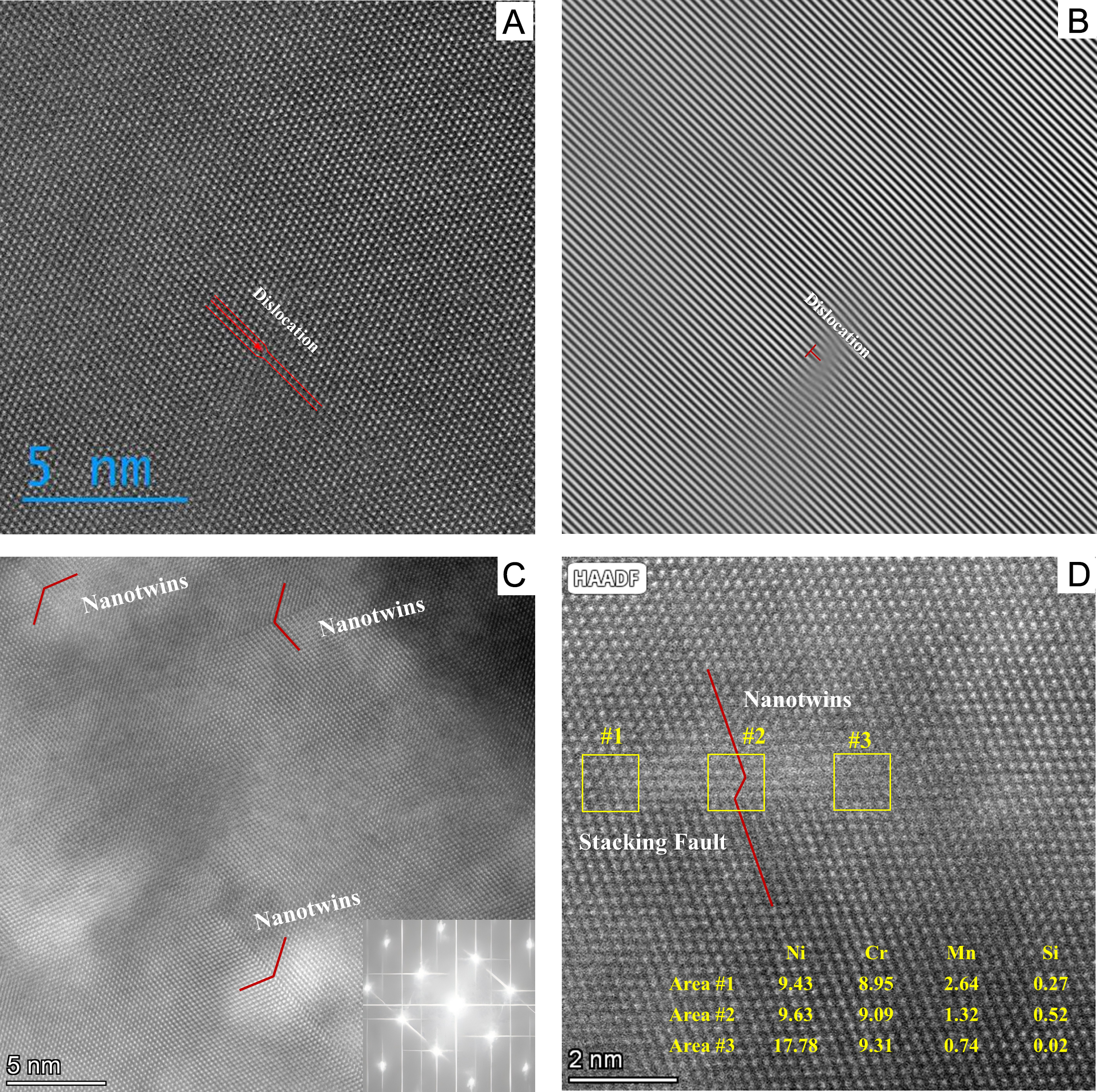
Figure 9. The atomic microstructure of FZ before and after cyclic loading at 4.2 K: (A) an STEM HAADF image of the FZ before fatigue, showing an edge dislocation, (B) IFFT of (A), (C) an STEM HAADF image of the FZ after fatigue, showing the formation of nanotwins, (D) the corresponding formation of nanotwins near the stacking faults in FZ after fatigue, with EDS results for individual elements of Ni, Cr, Mn, and Si, displaying the segregation of elements along the stacking faults and nanotwins. FZ: Fusion zone; STEM: scanning transmission electron microscopy; HAADF: high-angle annular dark-field; EDS: energy dispersive spectroscopy; IFFT: inverse fast Fourier transform.
DISCUSSION
The experimental results clearly reveal that the HAZ and FZ of 316LN welded joint follow different plasticity mechanisms during cyclic loading at 4.2 K. It is well established that the deformation mechanism depends primarily on the SFE of austenite[51,52]. Here, a thermodynamics-based method[53,54] was utilized to calculate the temperature dependent SFE of different regions in the current 316LN welded joint based on the following equations:
Calculations show that the SFE of 316LN BM is 33.60 mJ/m2 at 298 K, decreasing to 19.16 mJ/m2 at 4.2 K. For comparison, other reported values for 316LN stainless steel at 298 K are 30.14 mJ/m2 and 30.26 mJ/m2[54], which align well with our results. Within this SFE range, a lower SFE is known to promote twin formation, leading to an increased twin volume fraction, higher twin density, and refined twin size[55]. TEM observations highlight distinct faulting behaviors between the HAZ and FZ after fatigue [Figure 7 and 8]. In the HAZ, only stacking faults are observed, while the FZ exhibits both stacking faults and deformation twins, with a noticeably higher density of stacking faults. Since the HAZ shares the same composition as the BM, its SFE remains 19.16 mJ/m2 at 4.2 K. In contrast, the FZ displays significant elemental segregation at the interdendrite [Figure 5], locally reducing the SFE to 17.22 mJ/m2, whereas the SFE within the dendrites slightly increases to 19.66 mJ/m2. This local SFE reduction at the interdendrite promotes the formation of stacking faults and deformation twins in the FZ during cyclic loading at 4.2 K. Accordingly, differences in SFE suggest that the stacking fault and twin densities should vary between the dendritic and interdendritic regions. However, the overall defect densities are extremely low and the TEM sampling volume is limited, rendering reliable quantitative measurements difficult.
TEM analysis shows that the stacking faults in both HAZ and FZ are formed within grain interior, indicating that they originate from the dissociation of perfect dislocations during fatigue. To evaluate the probability of this dissociation process for forming wide stacking faults, we considered a perfect dislocation with a Burgers vector
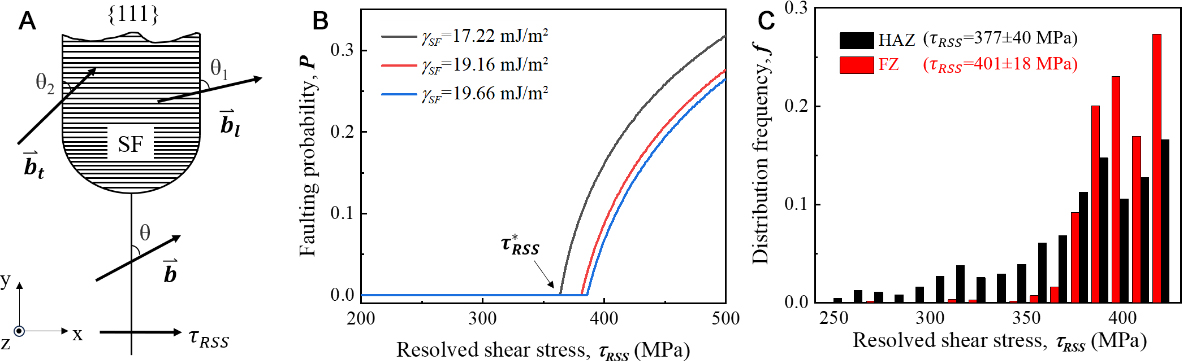
Figure 10. Analysis of perfect dislocation dissociation during fatigue loading: (A) schematic illustrating the dissociation of a perfect dislocation into leading and trailing Shockley partial dislocations on a {111} plane driven by applied resolved shear stress; (B) the probability of forming a wide stacking fault as a function of the resolved shear stress for different values of SFE; (C) the distribution frequency of resolved shear stress of grains with different Schmid factors in both the HAZ and FZ zones. SFE: Stacking fault energy; HAZ: heat-affected zone; FZ: fusion zone.
where γSF is SFE, and f0 represents the slip resistance due to the combined effects of lattice friction and solid solution in the current stainless steel. For simplicity, the interaction between the leading and trailing partials was neglected, as the interaction force decays rapidly with increasing separation distance[55].
To estimate f0, the flow resistance due to lattice friction and solid solution (σ0) was first determined using the Hall-Petch relation:
Assuming random dislocation orientations (θ ranging from 0° to 90°), the probability of wide stacking fault formation under certain applied stress was assessed by determining the angular range over which both conditions (1) and (2) are satisfied. Additionally, both leading and trailing partial dislocations must remain sessile when the applied stress decreases to around zero during cyclic tensile loading. Calculation confirms that
Figure 10B shows the probability of forming a wide stacking fault via dislocation dissociation as a function of resolved shear stress using the SFE values corresponding to HAZ, the subgrain boundary and the interior of FZ after fatigue. The probability remains zero below a critical resolved shear stress,
To further assess the faulting behavior, we analyzed the distribution of τRSS in the HAZ and FZ based on Schmid factors obtained from EBSD [Figure 2B] and a maximum applied tensile stress of 850 MPa during fatigue loading, as shown in Figure 10C. Due to the strong solidification texture in the FZ, Schmid factors are confined between 0.4 and 0.5, corresponding to τRSS values ranging from 340 to 425 MPa. In contrast, the HAZ, with its randomly oriented grains, exhibits a wider Schmid factor distribution, resulting in τRSS values from 250 MPa to 425 MPa. This indicates that the local resolved shear stress is higher in the FZ than in the HAZ. The total probability of forming a wide stacking fault (Ptw) was calculated by summing the product of the dissociation probability, P(τRSS), and the frequency distribution, f(τRSS): Ptw = ∑P(τRSS) ∙ f(τRSS). The result shows that Ptw for the FZ (0.157) is over three times that of the HAZ (0.053), explaining the higher density of stacking faults and the formation of nanotwins in the FZ after fatigue [Figures 7 and 8]. In summary, these evaluations demonstrate that stacking faults form more readily in the FZ after fatigue due to both the reduced SFE from elemental segregation at subgrain boundaries and the elevated local resolved shear stress associated with the solidification texture. Additionally, the analysis also highlights the importance of slip resistance in preventing the backward movement of the leading partial dislocation - and hence the collapse of stacking faults - during unloading in cyclic loading.
It is commonly shown that the laser welding process leads to a fluctuation in the content of various elements in the FZ compared to the HAZ[58]. Such compositional variations not only act as obstacles to dislocation glide by enhancing solid solution strengthening, but also locally adjust the SFE, reducing the critical stress for twin nucleation and increasing the number of nucleation sites. This observation is consistent with the findings of Wang et al.[43], who reported that solute segregation along cellular walls and low-angle grain boundaries enhances dislocation pinning and twinning. As demonstrated in Figure 7, cross-slip is promoted in the HAZ with a relatively high SFE during fatigue, resulting in only a minor increase in dislocation density (~8%), from an initial GND density of 3.02 × 10¹³ m-2 to 3.26 × 10¹³ m-2 after fatigue [Table 1]. In contrast, dislocations in the FZ (i.e., a low-SFE region) are confined to planar slip and readily dissociate into partials, inhibiting cross-slip. This leads to enhanced dislocation accumulation, causing a significant increase in dislocation density (~37.6%), from 1.86 × 10¹³ m-2 to 2.56 × 10¹³ m-2 after fatigue. This higher dislocation density intensifies local stress concentrations under cyclic loading. Liu et al. and Li et al.[59,60] proposed to correlate the slip mode to a unified evolution factor: α = ys/dex, where ys is the annihilation distance and dex is width of stacking fault. Larger evolution factors correspond to narrower stacking faults and greater annihilation distances, which favor wavy slip with frequent cross-slip. Conversely, smaller evolution factors result in wider stacking faults, reduced annihilation distances, and suppressed cross-slip, leading to planar slip. Similarly, Shih et al.[61] highlighted that SFE governs dislocation mobility, cross-slip capability and twin formation in face-centered cubic (FCC) crystals. A lower SFE restricts cross-slip, promotes planar slip, and facilitates twin formation, resulting in twinning-assisted plasticity in the FZ. Additionally, reduced SFE enhances planar slip by limiting dislocation annihilation and enabling greater dislocation pile-ups, which in turn activate stacking faults and nanotwins, introducing dynamic Hall-Petch effect. Thus, the combined effects of higher dislocation density and nanotwin formation contribute to the increased normalized hardness observed in certain local regions within the FZ after fatigue. TEM observations confirm that L-C locks form more readily in the FZ than in the HAZ [Figure 8]. The formation of L-C locks requires the glide of Shockley partial dislocations on both primary and conjugate slip planes. In the FZ, the lower SFE in interdendritic regions promotes partial dislocation activity, increasing the probability of L-C lock formation. Furthermore, the solidification-induced texture in the FZ provides a higher Schmid factor for partial dislocation slip, offering a stronger driving force that further facilitates L-C lock nucleation. Deformation-induced martensitic transformation typically occurs when the SFE drops below ~20 mJ/m2[62]. In the present sample, the lowest SFE - 17.22 mJ/m2 - occurs in the interdendritic regions of the FZ, near the upper limit for such transformation. Under these conditions, martensitic transformation is difficult to initiate. Additionally, the plastic strain induced during high-cycle fatigue at 4.2 K is minimal, further preventing the formation of martensite. Together, these factors explain the absence of martensitic transformation in this sample.
CONCLUSIONS
In this study, the microstructural evolution and plasticity mechanisms of 316LN stainless steel laser-welded joints under cyclic loading at 4.2 K were systematically investigated through a combination of experiments and theoretical analysis. The main conclusions are drawn as follows:
1. The welded joint maintains a stable single-phase austenitic structure both before and after fatigue, with no evidence of martensitic transformation. The FZ consists of large columnar grains with dendritic substructures. Elemental mapping reveals Cr, Mn and Mo segregation at the interdendrite in the FZ, leading to localized reductions in SFE compared to the HAZ.
2. Dislocation densities increase in both the HAZ and FZ after fatigue, with the FZ exhibiting a significantly greater rise. The HAZ primarily accommodates plastic deformation through wavy dislocation slip, while the FZ is characterized by planar slip, a higher density of stacking faults and the formation of deformation twins.
3. The promoted formation of stacking faults and nanotwins in the FZ is attributed to two key factors: the locally-reduced SFE in the interdendrite, which lowers the critical stress required for wide stacking fault formation via dislocation dissociation; and the solidification-induced texture, which increases the local Schmid factor and thereby raises the resolved shear stress for promoting the nucleation of stacking faults and nanotwins.
4. Lomer-Cottrell locks are observed in the FZ as a result of dominant planar slip, contributing to dislocation multiplication. In contrast, such locks are absent in the HAZ due to its relatively higher local SFE, which favors more wavy and cross-slip dominated dislocation motion.
DECLARATIONS
Authors’ contributions
Methodology, investigation, writing - original draft: Gong, X.
Conceptualization, supervision, writing - review and editing: Xin, J.
Formal analysis, validation: Zhang, H.
Project administration, acquisition of data: Zhao, H.
Visualization, software: Zhu, M.
Data curation: Huang, C.
Funding acquisition, acquisition of data: Shen, F.
Investigation: Lyu, B.
Supervision, writing - review and editing: Liang, Z.; Wang, W.
Funding acquisition, resources, acquisition of data: Li, L.
Availability of data and materials
The raw data supporting the conclusions of this article are available from the corresponding author upon reasonable request.
AI and AI-assisted tools statement
During the preparation of this manuscript, the AI tool ChatGPT (version 5.5, released 2026-04-23) was used solely to polish the graphical abstract. The tool did not influence the study design, data collection, analysis, interpretation, or the scientific content of the work. All authors take full responsibility for the accuracy, integrity, and final content of the manuscript.
Financial support and sponsorship
This work was supported by the National Key Research and Development Program of China (Grant
Conflicts of interest
Gong, X.; Zhao,H. and Wang, W. are affiliated with China Nonferrous Metals Innovation Institute (Tianjin) Co., LTD., while the other authors have declared that they have no conflicts of interest.
Ethical approval and consent to participate
Not applicable.
Consent for publication
Not applicable.
Copyright
© The Author(s) 2026.
Supplementary Materials
REFERENCES
1. Zheng, C.; Yu, W. Effect of low-temperature on mechanical behavior for an AISI 304 austenitic stainless steel. Mater. Sci. Eng. A. 2018, 710, 359-65.
2. Wang, P.; Xu, Z.; Zhang, P.; et al. The highest fatigue strength for steels. Acta. Mater. 2025, 289, 120888.
3. Xu, Z.; Su, X.; Zhang, P.; et al. How high can the fatigue strength of metals be achieved? Natl. Sci. Rev. 2025, 12, nwaf332.
4. Wang, D.; Wang, Q.; Li, X.; Zhang, Z. Improving fatigue properties of 316L stainless steel welded joints by surface spinning strengthening. Acta. Metall. Sin. 2024, 37, 840-54.
5. Sgobba, S.; Dalin, J.; Langeslag, S. A. E.; et al. Qualification of structural stainless steel products for the ITER correction coil cases. Fusion. Eng. Des. 2017, 124, 980-4.
6. Xie, L.; Zhang, H.; Xin, J.; et al. Cryogenic spatiotemporal characteristics and microevolution of 316LN discontinuous plastic flow. Commun. Mater. 2025, 6, 159.
7. Xin, J.; Zhang, H.; Sun, W.; et al. Microstructure evolution of austenitic stainless steels under high-cycle-fatigue loading at deep cryogenic temperature. Scr. Mater. 2023, 226, 115223.
8. Li, J.; Zhou, Z.; Wang, S.; et al. Deformation mechanisms and enhanced mechanical properties of 304L stainless steel at liquid nitrogen temperature. Mater. Sci. Eng. A. 2020, 798, 140133.
9. Schneider, M.; Laplanche, G. Effects of temperature on mechanical properties and deformation mechanisms of the equiatomic CrFeNi medium-entropy alloy. Acta. Mater. 2021, 204, 116470.
10. Xiong, H.; Li, Y.; Xu, C.; Li, W.; Jia, X. Influences of dislocation configuration and texture optimization on obtaining exceptional cryogenic strength-ductility synergy in a dynamic-recovered heterogeneous high-manganese steel. Int. J. Plast. 2025, 185, 104225.
11. Byun, T.; Hashimoto, N.; Farrell, K. Temperature dependence of strain hardening and plastic instability behaviors in austenitic stainless steels. Acta. Mater. 2004, 52, 3889-99.
12. Obst, B.; Nyilas, A. Experimental evidence on the dislocation mechanism of serrated yielding in f.c.c. metals and alloys at low temperatures. Mater. Sci. Eng. A. 1991, 137, 141-50.
13. Skoczeń, B.; Bielski, J.; Tabin, J. Multiaxial constitutive model of discontinuous plastic flow at cryogenic temperatures. Int. J. Plast. 2014, 55, 198-218.
14. Madivala, M.; Schwedt, A.; Wong, S. L.; Roters, F.; Prahl, U.; Bleck, W. Temperature dependent strain hardening and fracture behavior of TWIP steel. Int. J. Plast. 2018, 104, 80-103.
15. Xin, J.; Zhang, H.; Lyu, B.; et al. Mechanical performance and deformation mechanisms of ultrastrong yield strength Fe-Cr-Ni-Mn-N austenitic stainless steel at 4.2 Kelvin. J. Mater. Sci. Technol. 2024, 189, 191-202.
16. Cui, C.; Weng, Z.; Gu, K.; Zhang, M.; Wang, J.; Zhang, Y. The strengthening role of post-welded cryogenic treatment on the performance and microstructure of 304 austenitic stainless steel weldments. J. Mater. Res. Technol. 2024, 29, 5576-84.
17. Ma, Y.; Naeem, M.; Zhu, L.; et al. Microscopic insights of the extraordinary work-hardening due to phase transformation. Acta. Mater. 2024, 270, 119822.
18. Li, X.; Ding, W.; Cao, J.; Ye, L.; Chen, J. In situ TEM observation on martensitic transformation during tensile deformation of SUS304 metastable austenitic stainless steel. Acta. Metall. Sin. 2015, 28, 302-6.
19. Liu, J.; Luo, X.; Huang, B.; et al. Nano-twinning and martensitic transformation behaviors in 316L austenitic stainless steel during large tensile deformation. Acta. Metall. Sin. 2022, 36, 758-70.
20. Zhao, Y.; Peng, K.; Wen, W.; et al. Coupled effects of TRIP and TWIP in metastable austenitic stainless steel via optimization of stacking fault energy. Mater. Charact. 2025, 220, 114656.
21. Shao, C.; Zhang, P.; Zhu, Y.; Zhang, Z.; Pang, J.; Zhang, Z. Improvement of low-cycle fatigue resistance in TWIP steel by regulating the grain size and distribution. Acta. Mater. 2017, 134, 128-42.
22. Liu, C.; Dong, W.; Sun, J.; Lu, S. Effect of precipitation behavior and deformation twinning evolution on the mechanical properties of 16Cr-25.5Ni-4.2Mo superaustenitic stainless steel weld metals. Acta. Metall. Sin. 2024, 38, 338-52.
23. Zhang, H.; Huang, C.; Huang, R.; Li, L. Influence of pre-strain on cryogenic tensile properties of 316LN austenitic stainless steel. Cryogenics 2020, 106, 103058.
24. Sakurai, T.; Umezawa, O. Fracture toughness and martensitic transformation in type 316LN austenitic stainless steel extra-thick plates at 4.2 K. Mater. Sci. Eng. A. 2023, 862, 144122.
25. Wu, S.; Xin, J.; Xie, W.; et al. Mechanical properties and microstructure evolution of cryogenic pre-strained 316LN stainless steel. Cryogenics 2022, 121, 103388.
26. Liu, X.; Feng, H.; Wang, J.; et al. Mechanical property comparisons between CrCoNi medium-entropy alloy and 316 stainless steels. J. Mater. Sci. Technol. 2022, 108, 256-69.
27. Li, X.; Wei, Z.; Wang, X.; et al. Effect of cryogenic temperatures on the mechanical behavior and deformation mechanism of AISI 316H stainless steel. J. Mater. Res. Technol. 2023, 22, 3375-86.
28. Huang, M.; Wang, L.; Wang, C.; et al. Optimizing crack initiation energy in austenitic steel via controlled martensitic transformation. J. Mater. Sci. Technol. 2024, 198, 231-42.
29. Mao, W.; Gao, S.; Gong, W.; et al. Martensitic transformation-governed Lüders deformation enables large ductility and late-stage strain hardening in ultrafine-grained austenitic stainless steel at low temperatures. Acta. Mater. 2024, 278, 120233.
30. Li, S.; Withers, P. J.; Kabra, S.; Yan, K. The behaviour and deformation mechanisms for 316L stainless steel deformed at cryogenic temperatures. Mater. Sci. Eng. A. 2023, 880, 145279.
31. Son, K.; Jeon, S.; Paul, B. K.; Na, Y.; Lee, K.; Kim, Y. Extremely low temperature mechanical behavior of in-situ oxide containing 304L stainless steel fabricated by laser powder bed fusion. J. Mater. Sci. Technol. 2025, 234, 319-34.
32. Singh, C.; Lee, T.; Lee, K. H.; et al. Exceptional fatigue-resistant austenitic stainless steel for cryogenic applications. Appl. Mater. Today. 2024, 38, 102195.
33. Fu, Y.; Liu, Q.; Lv, Y.; et al. Microstructural and chemical dependences of fracture toughness in stainless steel welds at 4.2 K. Eng. Fract. Mech. 2024, 305, 110207.
34. Xin, J.; Fang, C.; Huang, C.; et al. Analysis of the fracture mechanism at cryogenic temperatures of thick 316LN laser welded joints. Fusion. Eng. Des. 2019, 148, 111277.
35. Mohanty, S.; Mukherjee, M.; Mandal, C.; et al. Understanding the microstructural evolution and tensile characteristics of low nickel austenitic stainless-steel welds fabricated by diode LASER. Int. J. Press. Vessel. Pip. 2023, 206, 105087.
36. Choudhury, B.; Singh, V.; Selvarajan, L.; Goel, S.; Chandrasekaran, M. Synergic investigation of microstructure, precipitation, and micro-segregation on inconel 825 weldments: a comparative study between GTAW and EBW. Mater. Chem. Phys. 2024, 318, 129249.
37. Qu, Z.; Zhang, Z.; Liu, R.; et al. High fatigue resistance in a titanium alloy via near-void-free 3D printing. Nature 2024, 626, 999-1004.
38. Gao, S.; Li, Z.; Van Petegem, S.; et al. Additive manufacturing of alloys with programmable microstructure and properties. Nat. Commun. 2023, 14, 6752.
39. Zhou, Y.; Shen, C.; Shi, H.; et al. Accurate determination of active slip systems using a novel lattice rotation analysis: quasi-in-situ EBSD/ECCI study on the homogeneous/heterogeneous deformation of polycrystalline zirconium. Materialia 2024, 36, 102176.
40. An, D.; Zaefferer, S. Formation mechanism of dislocation patterns under low cycle fatigue of a high-manganese austenitic TRIP steel with dominating planar slip mode. Int. J. Plast. 2019, 121, 244-60.
41. Wang, X.; He, P.; Zhou, Q.; et al. Effects of laser welding on the microstructure evolution and corrosion resistance of a novel nitrogen-containing austenitic stainless steel QN2109. J. Mater. Res. Technol. 2023, 24, 303-17.
42. Zhang, Z.; Li, Z.; He, Y.; Song, G.; Liu, L. The effect of low-power laser on micro-forming of 316 stainless steel additive manufacturing part. J. Manuf. Process. 2021, 68, 583-601.
43. Wang, Y. M.; Voisin, T.; Mckeown, J. T.; et al. Additively manufactured hierarchical stainless steels with high strength and ductility. Nat. Mater. 2017, 17, 63-71.
44. Gao, L.; Chen, Y.; Zhang, X.; Agnew, S. R.; Chuang, A. C.; Sun, T. Evolution of dislocations during the rapid solidification in additive manufacturing. Nat. Commun. 2025, 16, 4696.
45. Bertsch, K.; Meric De Bellefon, G.; Kuehl, B.; Thoma, D. Origin of dislocation structures in an additively manufactured austenitic stainless steel 316L. Acta. Mater. 2020, 199, 19-33.
46. Singh, B. P.; Sahoo, J. R.; Mishra, S. Elucidating the role of combined latent hardening due to slip-slip and slip-twin interaction for modeling the evolution of crystallographic texture in high nitrogen steels. Int. J. Plast. 2025, 185, 104215.
47. Shao, C.; Zhang, P.; Liu, R.; et al. A remarkable improvement of low-cycle fatigue resistance of high-Mn austenitic TWIP alloys with similar tensile properties: importance of slip mode. Acta. Mater. 2016, 118, 196-212.
48. Shen, S.; Xie, P.; Wu, C.; Luo, J.; Ye, H.; Chen, J. Cross-slip of extended dislocations and secondary deformation twinning in a high-Mn TWIP steel. Int. J. Plast. 2024, 175, 103922.
49. Vivekanandan, V.; Anglin, B.; El-azab, A. A data driven approach for cross-slip modelling in continuum dislocation dynamics. Int. J. Plast. 2023, 164, 103597.
50. Zhang, J.; Cao, G.; Gu, Z.; Wang, Z.; Jin, Y.; Liu, J. The modified Swift constitutive model of 304L stainless steel at the cryogenic temperature based on the Olson-Cohen model. Eng. Fract. Mech. 2024, 307, 110336.
51. Zou, Y.; Gao, Q.; Ding, H.; Zhang, Y.; Tang, Z. Investigations on austenite stability and martensitic transformation kinetics of a medium Mn steel under different strain states. Int. J. Plast. 2023, 171, 103788.
52. Lu, S.; Wang, Q.; Yao, T.; et al. Simultaneous improvement of strength and plasticity: nano-twin construction for a novel high-nitrogen TWIP steel. Int. J. Plast. 2024, 183, 104144.
53. Ishtiaq, M.; Kim, Y.; Tiwari, S.; et al. Serration-induced plasticity in phase transformative stainless steel 316L upon ultracold deformation at 4.2 K. Mater. Sci. Eng. A. 2025, 921, 147591.
54. Xie, L.; Zhang, H.; Wu, S.; et al. Development of two-dimensional temperature field solution method based on the stress-strain response of 316LN stainless steel at cryogenic temperatures. Cryogenics 2023, 133, 103713.
55. De Cooman, B. C.; Estrin, Y.; Kim, S. K. Twinning-induced plasticity (TWIP) steels. Acta. Mater. 2018, 142, 283-362.
56. Hong, C.; Lu, Y.; Zheng, H.; Li, Z.; Guo, G. Uniaxial tensile behaviors and Hall-Petch relationship of polycrystalline 316LN stainless steel via molecular dynamics simulation. Comput. Mater. Sci. 2024, 244, 113195.
57. Gordon, J.; Lim, R.; Wilkin, M.; Pagan, D.; Lebensohn, R.; Rollett, A. Evaluating the grain-scale deformation behavior of a single-phase FCC high entropy alloy using synchrotron high energy diffraction microscopy. Acta. Mater. 2021, 215, 117120.
58. Wang, X.; Tian, J.; Li, S.; He, P.; Fang, N.; Wen, G. Weldability of high nitrogen steels: a review. Rev. Adv. Mater. Sci. 2023, 62, 20220325.
59. Liu, R.; Tian, Y.; Zhang, Z.; Zhang, P.; An, X.; Zhang, Z. Exploring the fatigue strength improvement of Cu-Al alloys. Acta. Mater. 2018, 144, 613-26.
60. Li, P.; Li, S.; Wang, Z.; Zhang, Z. Unified factor controlling the dislocation evolution of fatigued face-centered cubic crystals. Acta. Mater. 2017, 129, 98-111.
61. Shih, M.; Miao, J.; Mills, M.; Ghazisaeidi, M. Stacking fault energy in concentrated alloys. Nat. Commun. 2021, 12, 3590.
Cite This Article
How to Cite
Download Citation
Export Citation File:
Type of Import
Tips on Downloading Citation
Citation Manager File Format
Type of Import
Direct Import: When the Direct Import option is selected (the default state), a dialogue box will give you the option to Save or Open the downloaded citation data. Choosing Open will either launch your citation manager or give you a choice of applications with which to use the metadata. The Save option saves the file locally for later use.
Indirect Import: When the Indirect Import option is selected, the metadata is displayed and may be copied and pasted as needed.
About This Article
Copyright

Data & Comments
Data
0


Comments
Comments must be written in English. Spam, offensive content, impersonation, and private information will not be permitted. If any comment is reported and identified as inappropriate content by OAE staff, the comment will be removed without notice. If you have any queries or need any help, please contact us at support@oaepublish.com.