



fig5
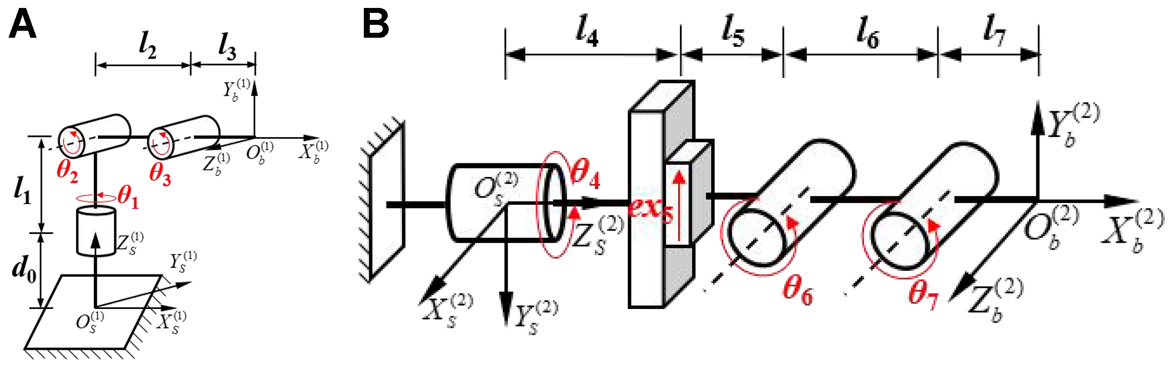
Figure 5. Screw coordinate systems of the harvesting robot. (A) Initial configuration of the positioning mechanism; (B) Initial configuration of the picking mechanism. OS(1) - XS(1)YS(1)ZS(1) and OS(2) - XS(2)YS(2)ZS(2) denote the base coordinate frames of the positioning mechanism and the picking mechanism, respectively; Ob(1) - Xb(1)Yb(1)Zb(1) and Ob(2) - Xb(2)Yb(2)Zb(2) denote the coordinate frames of the positioning base point and the end-effector (gripper) reference point, respectively.