


Triboelectric discharge based self-powered wireless sensing system for smart home application
 0
0 Abstract
The Internet of Things (IoT) holds significant potential for advancing smart home development. However, the challenge of maintaining a sustained power supply from batteries limits the widespread deployment of IoT systems. To address the critical issue of frequent battery replacement or recharging in IoT nodes, this work proposes a self-powered wireless sensing system (SWSS) that integrates graphene sharp-tip electrodes with a triboelectric nanogenerator. The non-metallic graphene electrodes, fabricated using laser-induced graphene technology, enable the system’s signal strength to match or even surpass that of similar self-powered systems employing metal electrodes. This facilitates efficient conversion and transmission of mechanical energy into electrical energy and wireless signals. The electrode distance, which affects signal quality, is optimized through COMSOL simulations; reducing the tip distance enhances signal generation up to a critical threshold. Experimental results demonstrate reliable signal transmission over distances exceeding five meters. A capacitance modulation method is developed to stabilize multi-frequency signal generation by making the modulation capacitance inversely proportional to signal frequency. Furthermore, the system operates stably for over 20,000 cycles, equivalent to a lifespan of more than 5.5 years. By integrating Braille into the sliding modules of four SWSS units, blind individuals can successfully control multiple devices in smart homes, highlighting the system’s potential for smart home and related applications.
Keywords
INTRODUCTION
With the advancement of human society into the era of intelligence, various sensing devices have become deeply integrated into daily life. This trend has led to an explosive growth in the demand for constructing sensor networks[1-3]. Traditional battery-powered sensor systems require frequent recharging or battery replacement, especially in large-scale deployments with high energy consumption or in remote applications where maintenance is inconvenient[4,5]. In this context, self-powered sensing systems that harvest environmental energy to enable autonomous operation present a promising and effective solution to address these technical challenges, offering broad prospects for development[6-8].
The piezoelectric nanogenerator (PENG) and the triboelectric nanogenerator (TENG) are both effective energy harvesting devices that capture environmental mechanical energy. However, the efficiency of PENGs is often limited by factors such as high resonance frequencies, narrow bandwidths, and low power output[9-11]. In contrast, TENGs offer significant advantages for harvesting low-frequency and irregular energy. Since its inception, TENG has demonstrated broad applicability in the field of high-entropy energy capture[12-15]. By coupling the contact electrification effect with electrostatic induction, TENGs can efficiently harvest various forms of environmental energy, including mechanical energy[16-19], wind energy[20,21], blue energy[22,23], human kinetic energy[24,25], and even bioenergy[26,27], providing sustainable power supplies for a wide range of sensors. Notably, in 2021, Wang et al. developed a self-powered wireless sensing e-sticker with precision-processed electrodes fabricated using the lithography method or electron beam evaporation techniques[28]. This technology triggers breakdown discharge through TENG, generating high-frequency displacement currents that directly produce electromagnetic wave signals without external power, offering a novel approach for wireless self-powered sensing. In 2023, Si et al. proposed a long-range multifunctional wireless sensing platform by cutting conductive copper strips adhered to a printed circuit board (PCB) with a scalpel, forming two mirror-symmetric metal electrodes with sharp tips, designed for multifunctional wireless sensing, including identification and ranging[29]. In 2024, Fu et al. further combined PCB substrates with electroless nickel/immersion gold techniques to develop a self-powered electronic nose sensing platform suitable for gas molecule recognition[30]. However, electrode fabrication in these studies often relies on complex integrated circuit manufacturing processes or suffers from the precision limitations and reproducibility challenges of manual operations. These issues pose significant challenges for the lightweight and rapid deployment of wireless self-powered sensing systems suitable for smart home applications.
Laser-induced graphene (LIG) technology enables the precise fabrication of porous graphene electrodes directly from specific carbon-containing precursor materials using a one-step laser writing process. This method offers significant advantages, including high efficiency, low cost, and great patterning flexibility. Due to its excellent electrical conductivity and outstanding mechanical properties, LIG has been successfully applied in various fields, such as self-powered sensors[31-33], supercapacitors[34,35], TENGs[36,37], and micro-robots[38,39], providing a novel technological pathway for the innovative development of TENG-based self-powered systems.
This paper presents an innovative design of a self-powered wireless sensing system (SWSS) that operates synergistically with LIG electrodes and TENGs. As shown in Supplementary Table 1, the SWSS employing non-metallic graphene electrodes demonstrates excellent performance compared to similar self-powered systems using metallic electrodes. The core working mechanism involves the TENG harvesting mechanical energy to generate charges, which produce high-frequency electromagnetic signals at the tip electrode structure through electrical discharge. Various capacitance components are configured to effectively modulate the signal frequency, and a coil is employed to enable remote wireless transmission and reception of the signals. Experimental results demonstrate that the system can effectively control multiple types of devices in typical household environments, exhibiting strong anti-interference capabilities and excellent durability.
EXPERIMENTAL
Fabrication and measurement of the TENG
A copper sheet measuring 50 mm by 70 mm with a thickness of 60 micrometers serves as the electrode for the freestanding-mode TENG (F-TENG) and is connected to wires. A polytetrafluoroethylene (PTFE) film, 100 μm thick and measuring 100 mm by 120 mm, functions as the dielectric layer. Both components are mounted on a suitably sized acrylic plate, and a commercially available nitrile butadiene rubber (NBR) glove is used as the friction layer to generate electrical energy. For electrical signal testing, a Keithley 6514 electrometer is employed. Since the measured voltage exceeds the instrument’s range, a voltage divider circuit comprising of resistors of 1 and 100 GΩ connected in parallel is used to measure voltages beyond the instrument’s range.
Fabrication of the tip electrode
The LIG technique is a well-established electrode fabrication process, with parameters based on our previous experimental results. The laser processing system operates at a wavelength of 355 nm, featuring a laser spot size of 27 μm, a power output of 2.1 W, and a scanning speed of 200 mm·s-1. Commercially available polyimide film (purchased from DuPont) is patterned using laser ablation to create the tip electrodes. Each electrode measures 15 mm in length and 10 mm in width, with a right-angled tip and a spacing of 100 micrometers between the tips. The electrodes are connected to copper leads via wires.
The receiver system
A wire with a diameter of 200 μm is wound around a coil with an inner diameter of 100 mm to form the transceiver coil, consisting of 10 turns. This coil is connected to a TBS2000B oscilloscope, creating the signal reception system. For electrical signal testing and analysis of the TENG, we use the PyVISA library (a Python interface for controlling measurement instruments) to remotely control the oscilloscope via a gateway address and configure its trigger mode to edge-triggered single-shot sampling. When a tip discharge occurs during TENG operation, the voltage excitation signal generated by this discharge can be accurately captured by the induction coil connected externally to the oscilloscope.
After the signal capture is completed, a program command triggers the oscilloscope to read the sampled data, transmitting the original electrical signal to a computer terminal. Subsequently, fast Fourier transform (FFT) processing is applied to the acquired time-domain signal, converting it into the frequency domain to enable frequency analysis. Finally, based on the frequency-domain characteristics, the tip discharge signal of the TENG is accurately identified, providing data support for subsequent evaluation of TENG output performance or investigation of discharge mechanisms.
RESULTS AND DISCUSSION
Design and working principle of SWSS
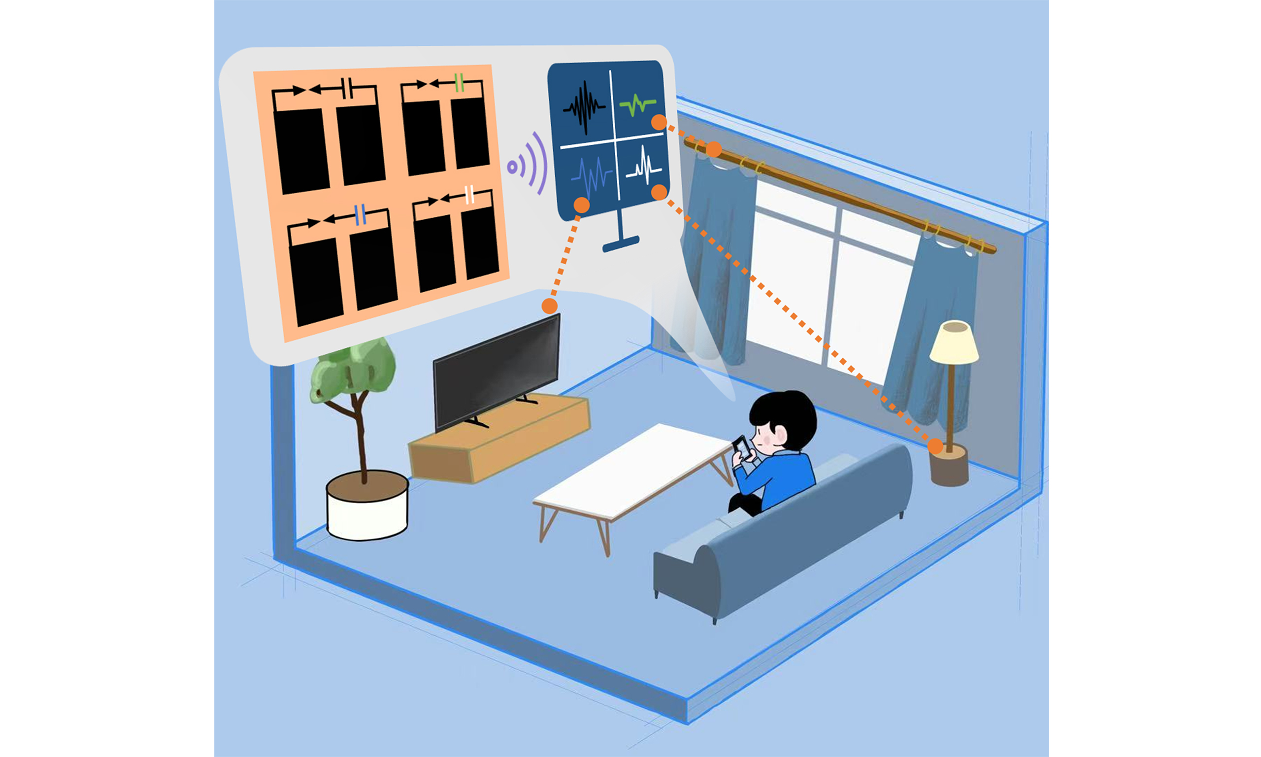
A schematic diagram of the SWSS is shown in Figure 1. The TENG used as the power supply operates in freestanding mode (F-TENG). NBR serves as the friction layer, PTFE functions as the dielectric layer, copper foil acts as the electrode, and an acrylic plate serves as the substrate for fixation. Utilizing the precise patterning capability of LIG, a pair of mirror-symmetric graphene electrodes with sharp tips is fabricated. The high curvature of these electrodes generates a locally enhanced electric field, significantly lowering the threshold for gas triboelectric discharge.
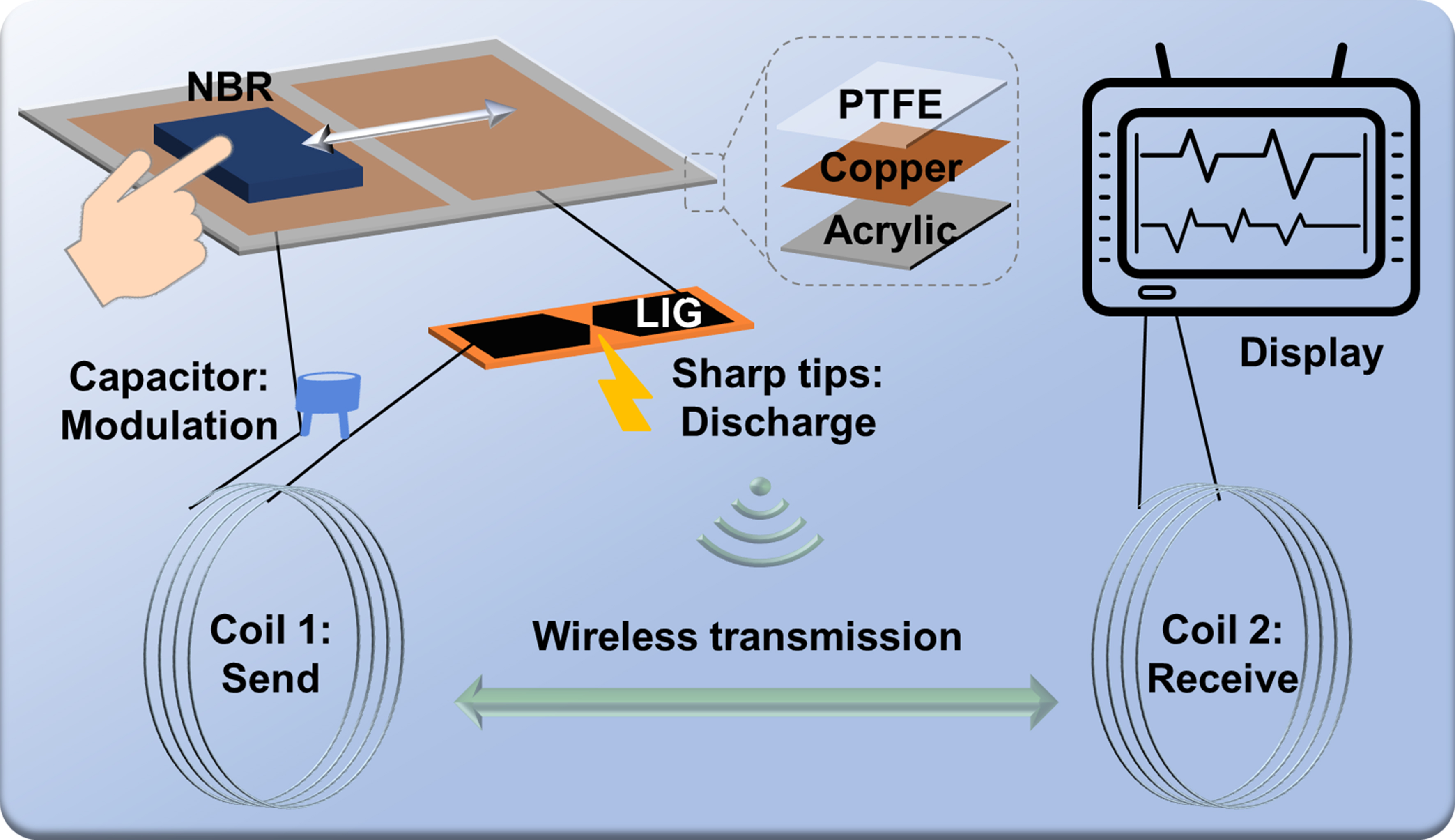
Figure 1. Schematic illustration of the SWSS based on F-TENG. SWSS: Self-powered wireless sensing system; F-TENG: freestanding-mode triboelectric nanogenerator; NBR: nitrile butadiene rubber; LIG: laser-induced graphene; PTFE: polytetrafluoroethylene.
The triboelectric discharge mechanism involves the generation of triboelectric charges when the NBR friction layer slides over the dielectric layer and electrodes. This charge separation facilitates a triboelectric discharge between the oppositely charged electrodes, producing high-frequency signals from low-frequency mechanical motion. By integrating a transmitting coil with a modulating capacitor, these high-frequency electrical signals can be wirelessly transmitted to a receiving coil connected to an oscilloscope for visualization and analysis. The entire energy conversion and information transmission process requires no external power supply, fully demonstrating the self-powered capability of the SWSS.
Enhanced output performance can generate triboelectric discharge signals with higher intensity and greater stability. To investigate the factors influencing the output performance of the F-TENG, a reciprocating motion platform designed to minimize testing error was constructed to trigger the F-TENG, as shown in Figure 2A. This platform can be customized to operate at various reciprocating frequencies of the NBR material on the PTFE dielectric layer. As illustrated in Figure 2B, when the reciprocating frequency increases from 0.5 to 1 and then to 1.3 Hz, the output current of the F-TENG rises from 2.46 to 7.36 and 13.1 μA, respectively, while the output voltage grows from 330.2 to 501.1 and 537.6 V. Further increasing the frequency to 1.6 Hz results in a relatively stable current of approximately 13.5 μA and a voltage of 572 V. However, the measurement error becomes significantly larger. Beyond this frequency, the contact between NBR and PTFE becomes unstable due to excessive velocity, which affects the consistency of the output. Therefore, reciprocating frequencies within the range of 1.3-1.6 Hz were selected for subsequent testing. Figure 2C depicts the influence of applied pressure on the output performance of the F-TENG. Different pressures were applied using weights, with masses increasing from 500 to 1,250 g, and the contact area was approximately 0.0015 m2. The pressure generated by these weights is also comparable to the pressure produced by human finger touch. As the applied pressure increased from approximately 3.3 kPa (500 g) to 4.9 kPa (750 g) and 6.5 kPa (1,000 g), the output current increased linearly from 4.9 to 8.2 and 12.8 μA, while the voltage rose linearly from 391 to 470.1 and 528.7 V. A further increase in pressure to about 8.2 kPa (1,250 g) resulted in a slight increase in current to approximately 13.1 μA and voltage to 537.6 V. This trend is attributed to improved contact intimacy between NBR and PTFE with larger applied force, which enhances charge exchange. Once the contact becomes fully intimate beyond a certain force, further increases in weight yield negligible improvements in output performance.
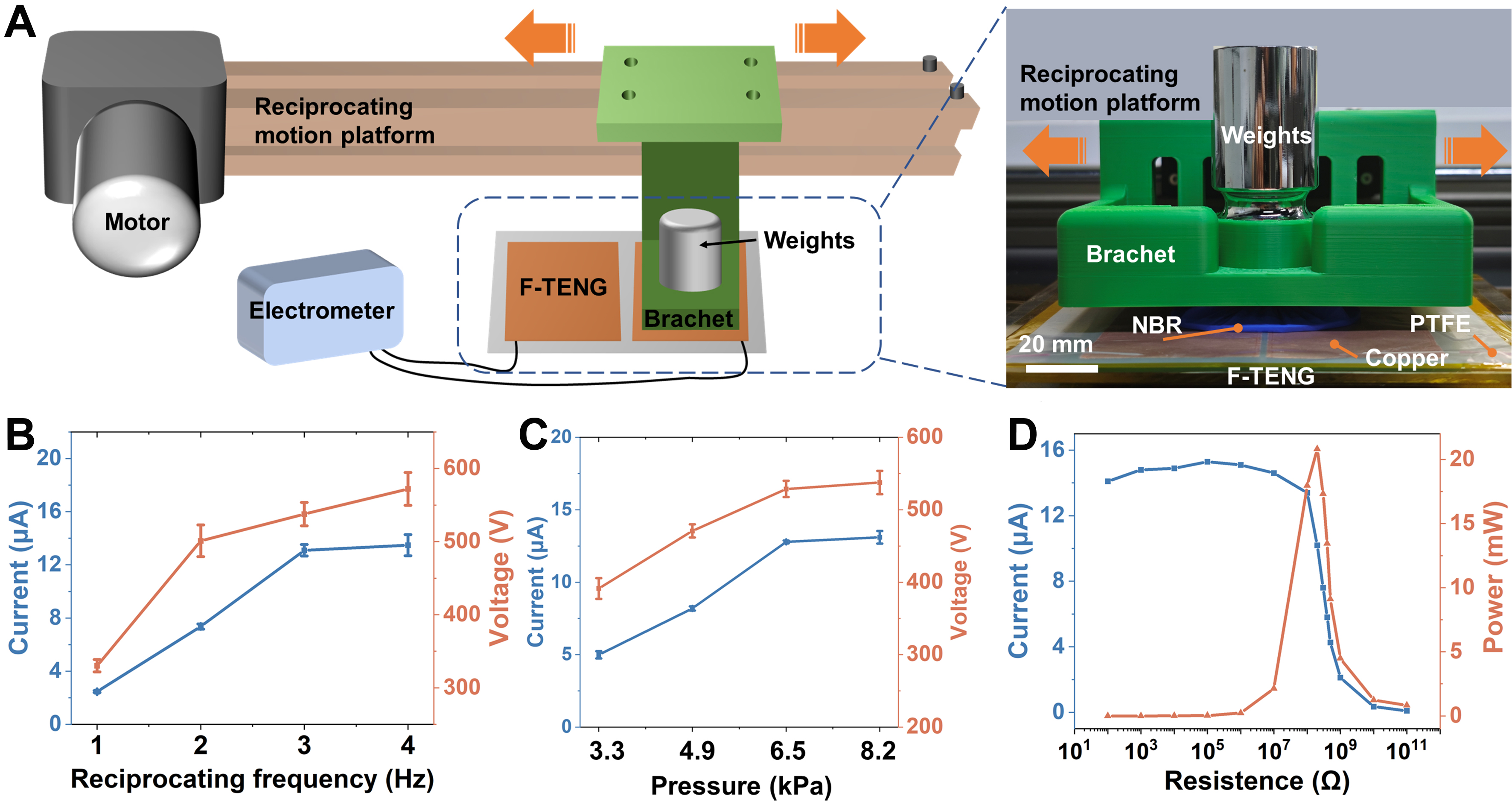
Figure 2. Output performance of the F-TENG. (A) Schematic diagram of the reciprocating motion platform; (B) Effect of reciprocating motion frequency on output performance; (C) Effect of external pressure on output performance; (D) Current and peak power measurements at different impedances. F-TENG: Freestanding-mode triboelectric nanogenerator; NBR: nitrile butadiene rubber; PTFE: polytetrafluoroethylene.
To provide critical data for the subsequent design of the equivalent circuit, the optimal load resistance and maximum power output were investigated. Figure 2D shows the peak current under various external load resistances ranging from 100 Ω to 100 GΩ. The corresponding power was calculated using P = I2R. When the load resistance was matched to 200 MΩ, the maximum power output of the F-TENG reached a peak value of 20.8 mW.
The triboelectric discharge mechanism of the SWSS is illustrated in Figure 3A. When the NBR friction layer slides over the dielectric layer on electrode 1, triboelectric charges are generated on the surfaces of the two materials: the NBR becomes positively charged, while the dielectric layer (PTFE) becomes negatively charged. To balance these charges, electrode 1 becomes positively charged through electrostatic induction. Similarly, when the friction layer slides over electrode 2, the electrode acquires a negative charge due to electrostatic induction from the positively charged friction layer. Because the two oppositely charged electrodes are separated by only 100 μm and have a large curvature, a triboelectric discharge occurs between them[40]. This discharge is accompanied by the generation of a high-frequency signal, converting low-frequency mechanical motion into high-frequency electrical signals.
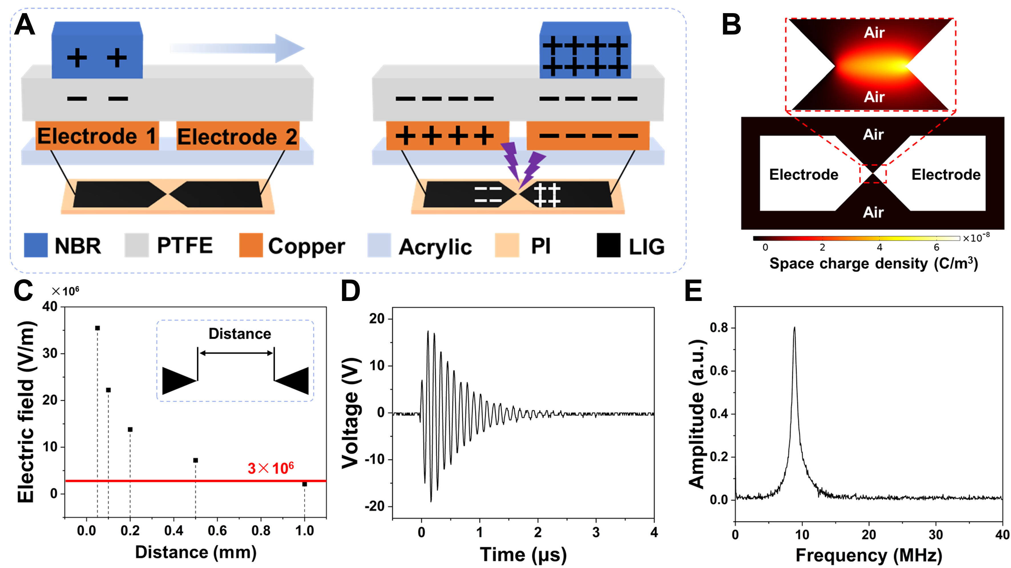
Figure 3. Systematic study of the SWSS signals. (A) Triboelectric discharge mechanism of sharp-tip electrodes; (B) COMSOL simulation model of electrodes with sharp tips; (C) Simulation results under different tip distances; Time-domain (D) and frequency-domain (E) diagrams of SWSS signals. SWSS: Self-powered wireless sensing system; NBR: nitrile butadiene rubber; PTFE: polytetrafluoroethylene; PI: polyimide; LIG: laser-induced graphene.
Since discharge phenomena occur at the highly curved sharp tips of the LIG electrodes, it is essential to investigate the influence of the tip geometry on the electromagnetic signal characteristics of the SWSS. Therefore, a discharge simulation model within an air medium was developed using COMSOL Multiphysics [Figure 3B] to optimize the geometric parameters of the sharp-tip electrode, thereby guiding the fabrication process to improve the stability of SWSS signals. Under an applied initial voltage of 500 V, which corresponds to the typical voltage provided by the F-TENG, the simulation results show that the maximum space charge density in the sharp-tip region reaches 6.8 × 10⁻⁸ C·m-3, with a peak electric field intensity of
A comparative analysis of simulation data for different tip-to-tip distances [Figure 3C] reveals that the maximum electric field intensity between the two tips exhibits a negative correlation with the tip-to-tip distance. When the distance is less than 1 mm, discharge conditions are already sufficient; furthermore, as the distance decreases, the field strength increases, thereby facilitating discharge. Based on this, the LIG fabrication should prioritize minimizing the tip-to-tip distance. Considering process constraints such as laser defocusing coverage and positional accuracy, the optimal tip-to-tip distance was ultimately determined to be 100 μm. The occurrence of a pronounced triboelectric discharge phenomenon during the process
Furthermore, after determining the optimal output power of the F-TENG and the ideal sharp-tip parameters, the maximum transmission distance of the SWSS signal was evaluated. As shown in Supplementary Figure 2A and Supplementary Video 1, the tests demonstrated a maximum transmission distance exceeding five meters, which already meets the requirements of typical smart home environments. Additionally, as shown in Supplementary Figure 2B and C, the tests revealed that even when a functioning electrical appliance and a strong magnet used to simulate common interference were placed in the middle of the transmission coil, the signal could still be reliably received at a distance of five meters. The comparison table in Supplementary Table 2 indicates that, compared to similar self-powered systems, SWSS achieves a comparable transmission distance. Supplementary Figure 2D illustrates the effects of signal transmission direction on the received signal quality. The results indicate that the signal strength remains consistent across the full range of electrode orientations; however, there is a slight increase in signal strength in the direction aligned with the electrode arrangement, likely due to the directional nature of the discharge phenomenon between the electrodes. This provides a solid foundation for the application scenarios discussed later.
Impact of environmental factors on SWSS signal transmission
To ensure reliable signal transmission in complex environments, a systematic assessment of signal penetrability is essential. As shown in Figure 4A, the distance between the transmitting and receiving coils is set to 200 mm. Several common materials, including wooden boards, polymers, metals, and magnetic media, are introduced sequentially for interference testing to simulate obstacles in a typical home environment. Figure 4B presents the time-domain and frequency-domain signals received under these conditions. The “Original” state, with no barrier material between the two coils, exhibits a characteristic signal amplitude of 17.5 V and a frequency of 8.8 MHz. When a 50 mm thick wooden board or a 30 mm thick polymer is introduced to simulate the door or desktop, the signal amplitude remains stable at 17 ±
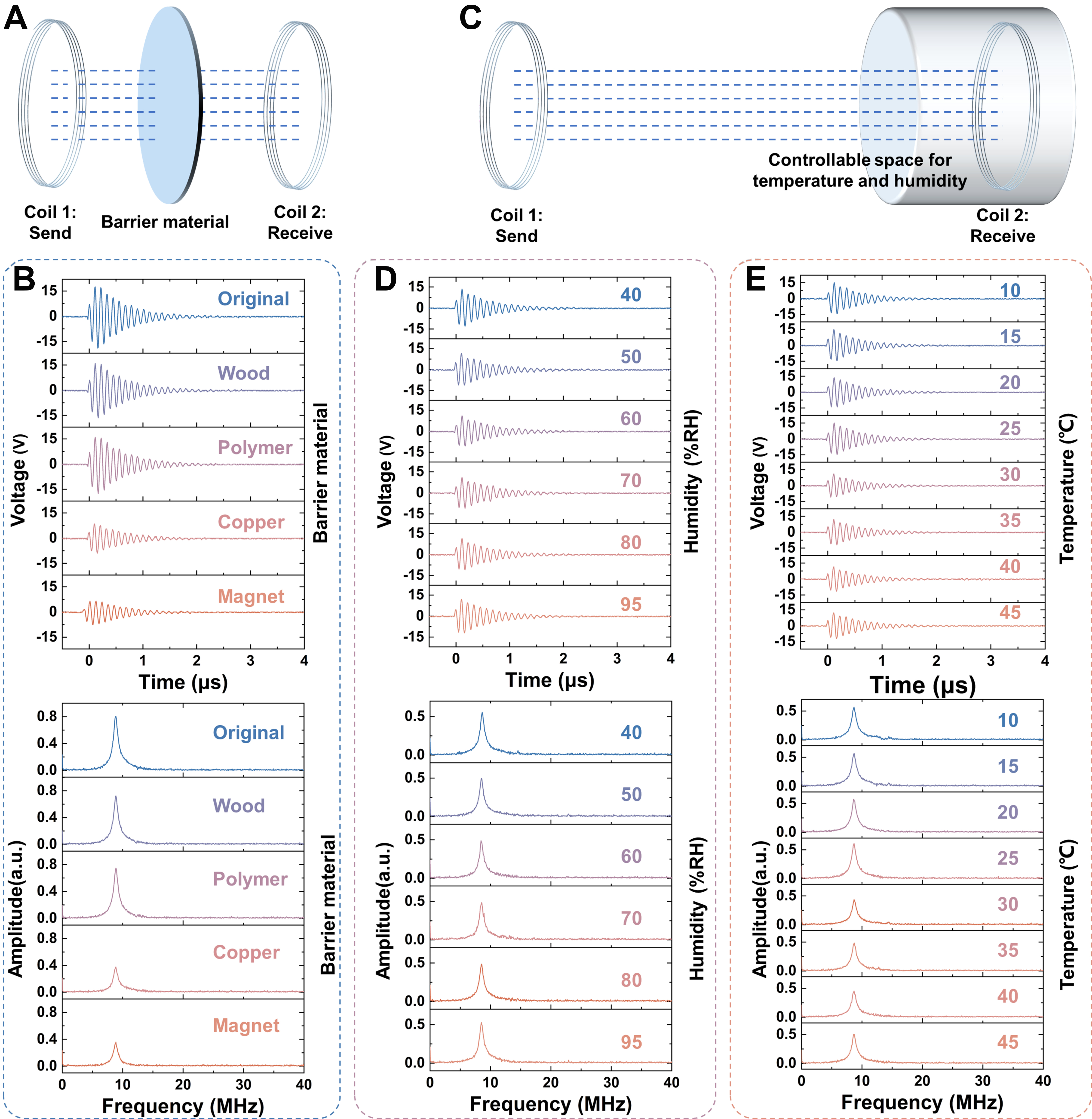
Figure 4. Impact of environmental factors on SWSS signal transmission. (A) Schematic of the barrier material test; (B) Time-domain and frequency-domain responses measured using different barrier materials; (C) Schematic of the climate chamber with controllable temperature and humidity; (D) Time-domain and frequency-domain responses under varying humidity conditions; (E) Time-domain and frequency-domain responses under varying temperature conditions. SWSS: Self-powered wireless sensing system.
To further quantify environmental influences, a temperature and humidity-controlled cavity testing platform was established [Figure 4C]. The signal receiving system was placed inside the cavity, and tests were conducted across a humidity range of 40%-95% relative humidity (RH) and a temperature range of 10-45 °C. The results show that the signal amplitude remained within 12 ± 2 V, and the frequency was stable at 8.8 ± 0.05 MHz [Figure 4D and E]. Additionally, electrodes were placed in an air environment for an extended period to simulate the effect of dust on signal generation during discharge. The results shown in Supplementary Figure 3 indicate that electrodes left in the air for 10 days or even up to 30 days produced signals with amplitudes similar to those of the original electrodes, approximately 11 V, with a consistent frequency of 8.8 MHz. These findings confirm that variations in humidity and temperature within typical household conditions do not alter the system’s signal frequency, demonstrating its stability and feasibility for application in smart home environments.
Signal modulation of the SWSS
As the entire system consists of measurable components such as resistors, capacitors, and inductors, the SWSS can be equivalently modeled as an inductor-resistor-capacitor (LRC) circuit[29,42], as illustrated in Figure 5A. This model incorporates the inherent capacitance of the F-TENG (CTENG) and the sharp-tip electrodes (CESD), as well as the inductances of the transmitting (Lem) and receiving coils (Lre), along with system resistances, Rem and Rre. The measured value of Lem is 16.2 μH, and the total capacitance C of the system comprises CTENG at 48.7 pF and CESD at 36.6 pF, which are connected in series. The calculated total capacitance is 20.9 pF. Using the classical resonance frequency, expressed as f =
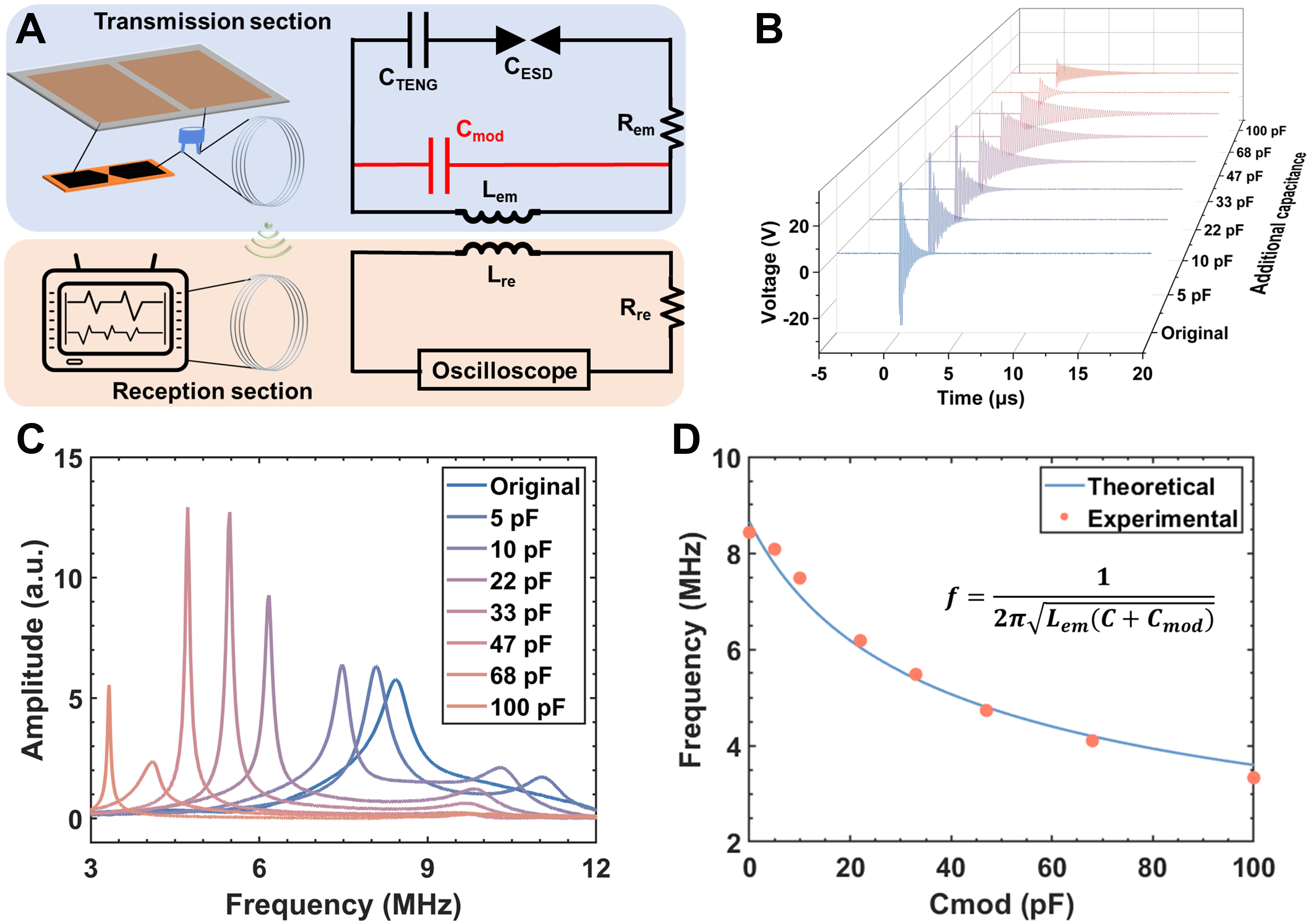
Figure 5. Signal modulation of the SWSS. (A) Connection and equivalent circuit model of SWSS; Time-domain (B) and frequency-domain (C) diagrams of signals with varying modulation capacitances; (D) Relationship between modulation capacitance and received signal frequency. SWSS: Self-powered wireless sensing system.
To further investigate the tunability of the system’s signal, the equivalent circuit of the SWSS was used to parallel-tune the capacitor Cmod, allowing for the examination of the relationship between the received signal spectrum and Cmod. Different capacitors were connected in parallel to the circuit, and the resulting received signal waveforms are shown in Figure 5B. Spectral analysis revealed a significant shift of the fundamental frequency toward lower frequencies [Figure 5C]. Since capacitance and frequency are inversely related, increasing the total capacitance by adding parallel capacitors leads to a decrease in the resonant frequency. By substituting the measured values, the theoretical f-Cmod curve is depicted in Figure 5D. The experimentally measured signal frequencies for various capacitance values show excellent agreement with the theoretical curve, validating the accuracy and effectiveness of the circuit model. Furthermore, these results demonstrate the feasibility of tuning wireless signals via parallel capacitor modulation.
The smart home application of SWSS
A smart home control system designed for visually impaired individuals was developed by integrating multiple SWSS units, leveraging the signal modulation characteristics of the SWSS [Supplementary Figure 4]. The system employs an acrylic substrate with PTFE as the dielectric layer material and copper sheets as the electrode material. By connecting the LIG sharp-tip electrodes and integrating the transmitting coil with the modulation capacitor, followed by housing installation, a complete SWSS functional unit is formed. Capacitors set at 5, 22, and 47 pF, along with a no-capacitance state, form four distinct signal frequency configurations. The action-trigger mechanism depicted in Figure 6A generates control signals for the precise operation of household appliances. Figure 6B shows the SWSS units operating at different frequencies, labeled “A”, “B”, “C”, and “D”. A scaled model simulating a living room environment has also been constructed [Supplementary Figure 5]. Additionally, corresponding Braille on the sliding module enhances usability for blind individuals. Experimental data [Figure 6C] indicate that the system employs a dual-state control logic, where the first triggered signal is defined as the “ON” command, and a second trigger of the same frequency executes the “OFF” operation. Specifically, “A”, “B”, and “D” correspond to independent control of the alarm, music, and ventilation, respectively, while “C” serves as a master control signal that can synchronize the management of multiple devices. In this experiment, functionality is validated by simultaneously controlling the switch states of devices “A” and “B” (demonstration video available as Supplementary Video 2). Durability testing [Supplementary Figure 6A] shows that the signals generated by the LIG sharp-tip electrodes maintain 65% of their peak strength after 20,000 triboelectric discharge cycles, with no frequency shift observed. Assuming an operational frequency of 10 times per day, the theoretical lifespan of the system exceeds 5.5 calendar years. Energy-dispersive X-ray spectroscopy (EDS) tests before and after the cycling of the tip electrode are shown in Supplementary Figure 6B and C. Results indicate that the carbon atom content of the LIG electrode decreased from 93.6% before the cycling to 90.5% after, suggesting that some LIG material was lost after discharge, which corresponds to the decrease in electrode performance. These experimental results validate the practical value of the SWSS in smart home scenarios and demonstrate the system’s potential for engineering applications.
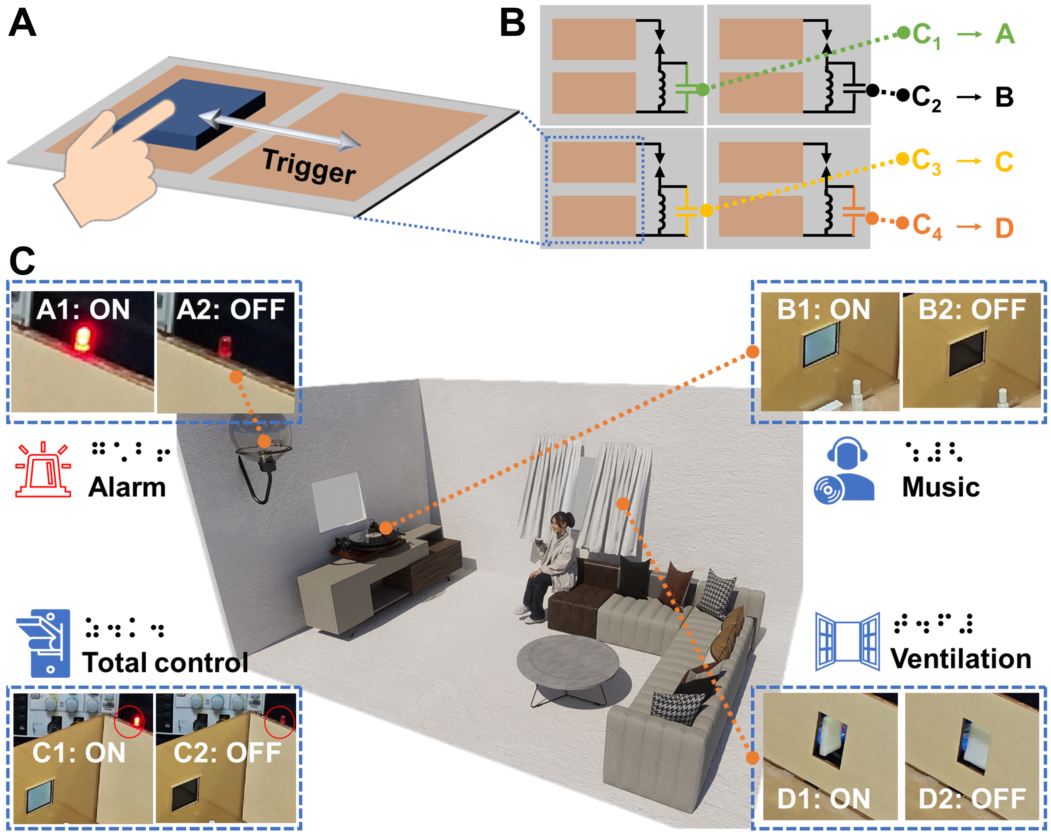
Figure 6. SWSS control demonstration for smart home applications. (A) Schematic of signal triggering; (B) Schematic of capacitance modulation differentiation; (C) Control results of appliances under various signal inputs. SWSS: Self-powered wireless sensing system.
CONCLUSIONS
This work proposes a SWSS based on triboelectric discharge effects. Electrodes with optimized sharp-tip structures were fabricated using a rapid, high-resolution and consistent LIG process, with parameters refined through COMSOL simulations. The use of non-metallic graphene electrodes, produced via LIG technology, enables the system to achieve signal strength comparable to or exceeding that of similar self-powered systems employing metal electrodes. The system integrates an F-TENG for energy harvesting and parallel-connected modulation capacitors with varying capacitance values. This design facilitates self-powered wireless transmission of programmable electrical signals during energy collection. Robustness tests confirm that the SWSS operates stably in environments with RH below 95% and a temperature range of 10-45 °C, demonstrating strong anti-interference capabilities and highlighting the tunability and environmental adaptability of the system. With a transmission range exceeding five meters, the SWSS shows practical applicability in smart home scenarios. A functional prototype incorporating four SWSS units with Braille sliders was developed, enabling visually impaired individuals to control household appliances independently or collectively through this device. The system maintained reliable performance over 20,000 operational cycles, corresponding to a lifespan exceeding 5.5 years. This study provides a novel strategy for integrating self-powered wireless sensing technologies into Internet of Things (IoT) frameworks.
DECLARATIONS
Authors’ contributions
Designed the SWSS and conducted the experiments: Xie, B.; Lin, S.
Developed the simulation model: Xie, B.
Contributed to the scientific discussion and experimental design: Xie, B.; Lin, S.; Guo, Y.; Chen, Y.; Hou, M.
Produced the graphic illustrations and prepared the videos: Xie, B.; Guo, Y.
Conceived the project: Chen, Y.
Serve as the supervisors: Chen, X.; Wong, C.
Wrote the manuscript with contributions from all authors: Xie, B.; Chen, Y.
All authors have given approval to the final version of the manuscript.
Availability of data and materials
Some results of supporting the study are presented in the Supplementary Materials. Other raw data that support the findings of this study are available from the corresponding author upon reasonable request.
Financial support and sponsorship
This work was supported by the National Natural Science Foundation of China (Grant 52422511), the Guangdong Basic and Applied Basic Research Foundation (Grant 2022B1515120011), the Guangzhou Basic and Applied Basic Research Foundation (Grants 2024A04J6362 and GZGX-24-01), the Zhuhai Industry-University-Research Cooperation Project (Grant 2320004002350), and China National Machinery Industry Corporation Research Special Project (ZDZX2024-18).
Conflicts of interest
All authors declared that there are no conflicts of interest.
Ethical approval and consent to participate
Not applicable.
Consent for publication
Not applicable.
Copyright
© The Author(s) 2025.
Supplementary Materials
REFERENCES
1. Yang, W.; Lin, S.; Gong, W.; et al. Single body-coupled fiber enables chipless textile electronics. Science 2024, 384, 74-81.
2. Cao, X.; Xiong, Y.; Sun, J.; Xie, X.; Sun, Q.; Wang, Z. L. Multidiscipline applications of triboelectric nanogenerators for the intelligent era of Internet of Things. Nanomicro. Lett. 2022, 15, 14.
3. Zhang, Q.; Xin, C.; Shen, F.; et al. Human body IoT systems based on the triboelectrification effect: energy harvesting, sensing, interfacing and communication. Energy. Environ. Sci. 2022, 15, 3688-721.
4. Xia, K.; Liu, J.; Li, W.; et al. A self-powered bridge health monitoring system driven by elastic origami triboelectric nanogenerator. Nano. Energy. 2023, 105, 107974.
5. Zeadally, S.; Shaikh, F. K.; Talpur, A.; Sheng, Q. Z. Design architectures for energy harvesting in the Internet of Things. Renew. Sustaina. Energy. Rev. 2020, 128, 109901.
6. Tang, W.; Sun, Q.; Wang, Z. L. Self-powered sensing in wearable electronics - a paradigm shift technology. Chem. Rev. 2023, 123, 12105-34.
7. Zhang, B.; Jiang, Y.; Ren, T.; Chen, B.; Zhang, R.; Mao, Y. Recent advances in nature inspired triboelectric nanogenerators for self-powered systems. Int. J. Extrem. Manuf. 2024, 6, 062003.
8. Xie, B.; Guo, Y.; Chen, Y.; et al. Advances in graphene-based electrode for triboelectric nanogenerator. Nanomicro. Lett. 2024, 17, 17.
9. Tian, Z.; Tsui, G. C.; Tang, Y. M.; Wong, C. H.; Tang, C. Y.; Ko, C. C. Additive manufacturing for nanogenerators: fundamental mechanisms, recent advancements, and future prospects. Nanomicro. Lett. 2025, 18, 30.
10. Gui, D.; Gao, Y.; Mi, X.; et al. Advancements in enhancement strategies for piezoelectric nanogenerator output performance and their applications in self-powered sensors. ACS. Sens. 2025, 10, 6292-315.
11. Gotte, M.; Rama Sreekanth, P. S. Integrating artificial intelligence with piezoelectric nanogenerators: a review on advancements in smart energy harvesting technologies. J. Mater. Sci. 2025, 60, 8253-84.
12. Choi, D.; Lee, Y.; Lin, Z. H.; et al. Recent advances in triboelectric nanogenerators: from technological progress to commercial applications. ACS. Nano. 2023, 17, 11087-219.
13. Du, T.; Chen, Z.; Dong, F.; et al. Advances in green triboelectric nanogenerators. Adv. Funct. Mater. 2024, 34, 2313794.
14. Li, Y.; Luo, Y.; Deng, H.; et al. Advanced dielectric materials for triboelectric nanogenerators: principles, methods, and applications. Adv. Mater. 2024, 36, e2314380.
15. An, J.; Jiang, Y.; Jiang, T.; et al. Achieving zero leakage, ultralong lifespan, and intrinsic opening sensing in microvalves through structural superlubrication and triboelectric nanogenerator technologies. Adv. Mater. 2025, 37, e2416132.
16. Li, G.; An, S.; Wang, P.; et al. Transverse-asymmetric electrode structure design to eliminate charge transfer loss for enhancing output performance of sliding mode TENG. Adv. Funct. Mater. 2025, 35, 2413359.
17. Xuan, N.; Song, C.; Cheng, G.; Du, Z. Advanced triboelectric nanogenerator based self-powered electrochemical system. Chem. Eng. J. 2024, 481, 148640.
18. Rani, G. M.; Wu, C.; Motora, K. G.; Umapathi, R.; Jose, C. R. M. Acoustic-electric conversion and triboelectric properties of nature-driven CF-CNT based triboelectric nanogenerator for mechanical and sound energy harvesting. Nano. Energy. 2023, 108, 108211.
19. Rani, G. M.; Wu, C.; Motora, K. G.; Umapathi, R. Waste-to-energy: utilization of recycled waste materials to fabricate triboelectric nanogenerator for mechanical energy harvesting. J. Clean. Prod. 2022, 363, 132532.
20. Gao, S.; Wei, H.; Wang, J.; et al. Self-powered system by a suspension structure-based triboelectric-electromagnetic-piezoelectric hybrid generator for unifying wind energy and vibration harvesting with vibration attenuation function. Nano. Energy. 2024, 122, 109323.
21. Wang, J.; Li, P.; Kang, X.; Li, Z.; Dai, S. Soft-soft contact TENG using nonlinear coupling galloping phenomenon for harvesting wind energy. Nano. Energy. 2025, 133, 110471.
22. Jiang, Y.; Liang, X.; Jiang, T.; Wang, Z. L. Advances in triboelectric nanogenerators for blue energy harvesting and marine environmental monitoring. Engineering 2024, 33, 204-24.
23. Shan, C.; He, W.; Wu, H.; et al. Dual mode TENG with self-voltage multiplying circuit for blue energy harvesting and water wave monitoring. Adv. Funct. Mater. 2023, 33, 2305768.
24. Umapathi, R.; Pammi, S.; Han, S.; et al. Designing smart anti-theft alarm system via lead-free BSFO-PDMS composite based triboelectric nanogenerator. Chem. Eng. J. 2025, 511, 161799.
25. Umapathi, R.; Rethinasabapathy, M.; Kakani, V.; et al. Hexagonal boron nitride composite film based triboelectric nanogenerator for energy harvesting and machine learning assisted handwriting recognition. Nano. Energy. 2025, 136, 110689.
26. Shen, D.; Du, T.; Dong, F.; et al. Advances of wearable silicone rubber-based triboelectric nanogenerators: from manufacturing to application. Int. J. Extrem. Manuf. 2025, 7, 032004.
27. Shi, A.; Luo, B.; Liu, W.; et al. A facile strategy for textile-based highly sensitive and water-resistant triboelectric nanogenerator. Adv. Mater. 2025, 37, e2420459.
28. Wang, H.; Wang, J.; Yao, K.; et al. A paradigm shift fully self-powered long-distance wireless sensing solution enabled by discharge-induced displacement current. Sci. Adv. 2021, 7, eabi6751.
29. Si, J.; Han, L.; Wang, R.; Wu, C.; Guo, M.; Li, J. Long-distance multifunctional wireless sensing platform for identifying and ranging. Nano. Energy. 2023, 109, 108267.
30. Fu, J.; Song, Z.; Wang, H.; et al. Deep-learning assisted biomimetic self-powered wireless electronic noses system enabled by triboelectric discharge. Nano. Energy. 2024, 121, 109156.
31. Gao, Z.; Wu, S.; Wei, Y.; et al. Holistic and localized preparation methods for triboelectric sensors: principles, applications and perspectives. Int. J. Extrem. Manuf. 2024, 6, 052002.
32. Li, Y.; Qin, M.; Lin, Q.; et al. Artificial intelligence motivated flexible single-electrode mode multilayer triboelectric sensor for smart mobility systems. Nano. Energy. 2024, 125, 109515.
33. Zhang, H.; Yang, H.; Xin, M.; et al. Thermoelectric composites based on porous laser-induced graphene and ion hydrogel. ACS. Appl. Mater. Interfaces. 2025, 17, 21773-84.
34. Fu, X.; Shu, R.; Ma, C.; Zhang, Y.; Jiang, H.; Yao, M. Self-assembled MXene-graphene oxide composite enhanced laser-induced graphene based electrodes towards conformal supercapacitor applications. Appl. Surf. Sci. 2023, 631, 157549.
35. Bayoumy, A. M.; Ibrahim, M. A.; Osman, A.; El-Moneim, A. A.; Hessein, A. Functionalized co-doped microporous carbon spheres for eco-friendly, high-performance and flexible supercapacitors. J. Power. Sources. 2025, 645, 237233.
36. Guo, W.; Xia, Y.; Zhu, Y.; Han, S.; Li, Q.; Wang, X. Laser-induced graphene based triboelectric nanogenerator for accurate wireless control and tactile pattern recognition. Nano. Energy. 2023, 108, 108229.
37. Pradhan, G. B.; Bhatta, T.; Shrestha, K.; Sharma, S.; Park, J. Y. A wearable, self-sustainable, and wireless plantar pressure and temperature monitoring system for foot ulceration prognosis and rehabilitation. Sens. Actuators. A. Phys. 2024, 379, 115985.
38. Mu, M.; Chen, G.; Yu, W.; et al. In situ growth of laser-induced graphene on flexible substrates for wearable sensors. ACS. Appl. Nano. Mater. 2024, 7, 3279-88.
39. Wang, W.; Han, B.; Zhang, Y.; et al. Laser-induced graphene tapes as origami and stick-on labels for photothermal manipulation via marangoni effect. Adv. Funct. Mater. 2021, 31, 2006179.
40. Ma, Z.; Zhou, Y.; Xia, J.; et al. Experimental study on corona onset characteristics of small curvature electrode under combined AC–DC voltages. IEEE. Trans. Dielect. Electr. Insul. 2022, 29, 1785-94.
41. Dong, K.; Hu, D.; Li, S.; et al. Wireless bubble detection enabled by triboelectric discharge. Nano. Energy. 2025, 142, 111159.
Cite This Article
How to Cite
Download Citation
Export Citation File:
Type of Import
Tips on Downloading Citation
Citation Manager File Format
Type of Import
Direct Import: When the Direct Import option is selected (the default state), a dialogue box will give you the option to Save or Open the downloaded citation data. Choosing Open will either launch your citation manager or give you a choice of applications with which to use the metadata. The Save option saves the file locally for later use.
Indirect Import: When the Indirect Import option is selected, the metadata is displayed and may be copied and pasted as needed.
About This Article
Copyright

Data & Comments
Data
0


Comments
Comments must be written in English. Spam, offensive content, impersonation, and private information will not be permitted. If any comment is reported and identified as inappropriate content by OAE staff, the comment will be removed without notice. If you have any queries or need any help, please contact us at support@oaepublish.com.