


fig4
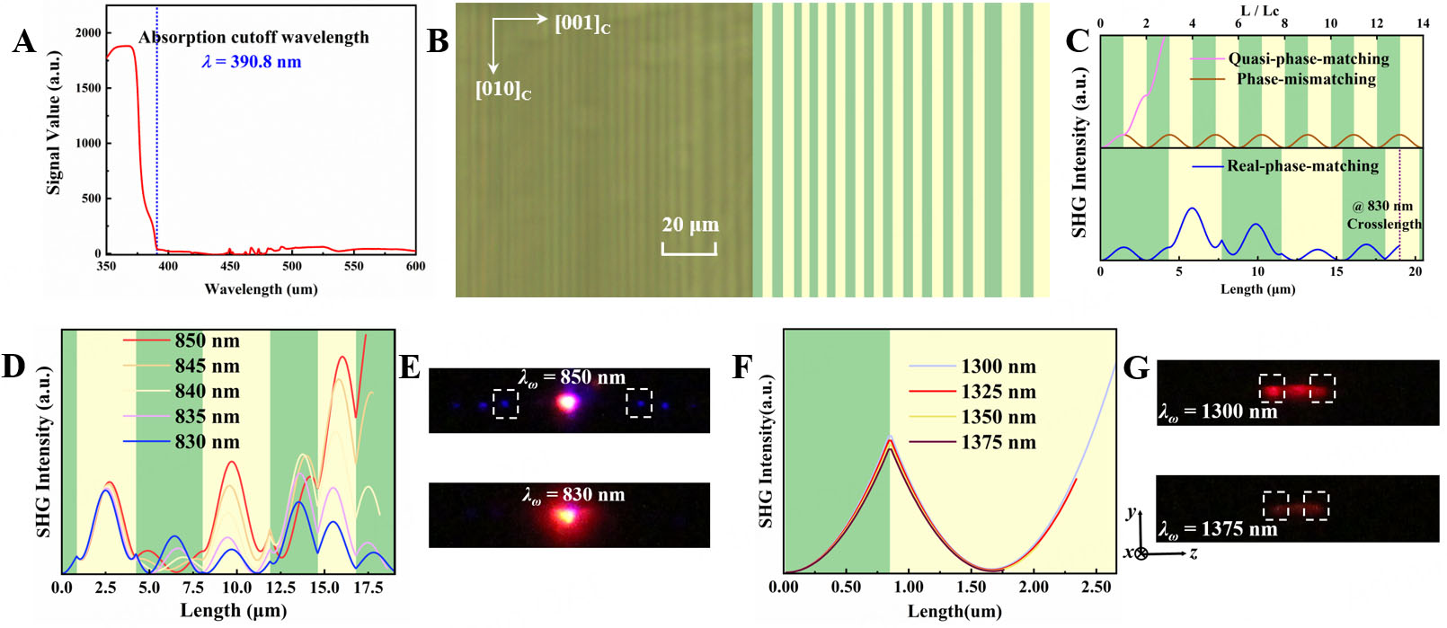
Figure 4. (A) Transmission spectrum of the stably poled KTN. (B) Polarization microscope image and corresponding deff distribution diagram (dark color represents positive and light color represents negative) of stably poled KTN in the y-z plane. (C) Schematic of the relationship between SHG (Type-I, at 830 nm FW) intensity and propagation distance under quasi-phase-matching, phase-mismatching, and real-space-matching. The intensity range is the same in both the upper and lower parts. Schematic of SHG change vs. fundamental wavelength (D) from 830 to 850 nm, with an interval of 5 nm, and (F) from 1,300 to 1,375 nm, with an interval of 25 nm. SHG spot patterns at (E) λω = 830 and 850 nm, (G) λω = 1,300 and 1,375 nm. The white dashed box encloses the SHG spots generated by the Type-I QPM process.


