Microscopic insights into the mechanical behavior of a Ni-Co-based superalloy through in-situ neutron diffraction
Abstract
The micromechanical behaviors and dislocation evolution in a polycrystalline Ni-Co-based superalloy were systematically investigated by in situ neutron diffraction tensile testing combined with line profile analysis. The results reveal the sequential activation of γ′ shearing and Orowan looping mechanisms, with interphase load partitioning governed by strain-dependent interactions of dislocation and precipitate. During the initial plastic deformation, the γ and γ′ phases undergo co-deformation through dislocation shearing without load transfer, while the Orowan looping facilitates the load transfer from γ to γ′ phase at a higher strain level. Furthermore, the low stacking fault energy leads to a rising fraction of screw dislocations by suppressing cross-slip. Crucially, the pinning effect of γ′ precipitates hinders the rearrangement of these dislocations into low-energy structures, resulting in the formation of high-energy, weakly screened dislocation configurations. These findings provide new evidence for the planar slip dominance in Ni-Co-based superalloys, enabling quantitative assessment of microstructural evolution and micromechanical responses.
Keywords
INTRODUCTION
Ni-based superalloys are extensively utilized in aerospace engines, gas turbines, and nuclear energy applications owing to their excellent comprehensive high-temperature properties[1,2]. Modern aeroengine turbine disks primarily utilize wrought superalloys, with their main strengthening mechanisms being γ′ or γ′′ precipitation strengthening[3,4]. Through continuous optimization of the high-temperature stability of γ′/γ′′ precipitates and the incorporation of additional strengthening and deformation mechanisms, the service temperature of wrought superalloys for turbine disks has been progressively elevated to approximately
With the advancement of neutron sources and strain scanners, in situ neutron diffraction presents incomparable advantages over conventional microscopy analysis, allowing for capturing the micromechanical dynamic responses and internal stresses of superalloys. Daymond et al.[16] discovered a load transfer from γ′ to γ up to 500 °C, while the reverse phenomenon occurred at higher temperatures. Additionally, the load transfer between γ and γ′ phases depends on the precipitate size and the deformation temperature, with the load transfer becoming more pronounced as precipitate size and temperature increase[17]. Load transfer herein refers to the redistribution of local stress resulting from differential yielding between microstructural constituents. In polycrystalline Ni-based superalloys, load transfer includes two primary modes: (i) Intergranular transfer occurs from high-stiffness grains {e.g., {110}} to low-stiffness grains {e.g., {001}}, governed by crystallographic anisotropy; (ii) Interphase transfer takes place from the γ matrix to γ′ precipitates when plastic deformation arises in the γ but not in the γ′ phase, driven by γ/γ′ property mismatch. Both mechanisms obey the stress equilibrium constraint
In the present study, an in situ neutron diffraction tensile test was conducted on a Ni-Co-based superalloy to unveil the micro-mechanical responses of the γ and γ′ phases. The evolution of dislocation structures throughout the entire deformation process was evaluated by the CMWP procedure combined with postmortem electron-microscopic analysis. These experimental findings give deep insights into the mechanical behaviors and dislocation arrangements, which contribute to developing accurate predictive models for the material properties and component performance.
MATERIALS AND METHODS
An advanced Ni-Co-based superalloy was adopted in this work, which combines superior high-temperature properties and excellent hot workability[10,14,32]. The nominal chemical composition of the alloy is shown in Table 1. The as-received alloy was a forged bar and subjected to a solution heat treatment at 1,100 °C for 1 h, followed by oil quenching. Subsequently, a two-step aging treatment was performed at 650 °C for 24 h and 760 °C for 16 h, respectively. Microstructural observation and grain orientation analysis were performed using a ZEISS Gemini 450 field emission scanning electron microscope (SEM) equipped with an Oxford Symmetry Electron backscattered diffraction (EBSD) detector. Additionally, the deformation mechanisms of the alloy were investigated using SEM-based electron channeling contrast imaging (ECCI) combined with a FEI Tecnai F20 transmission electron microscope (TEM).
Chemical composition of Ni-Co-based superalloy in wt.%
| Alloy | Ni | Co | Cr | Mo+W | Al | Ti | Nb+Ta | C | B |
| wt.% | Bal. | 23~27 | 10~15 | 3~5 | 2~3 | 3~5 | 1~3 | 0.01~0.05 | 0.01~0.05 |
In situ neutron diffraction tensile measurement was performed at room temperature using the engineering materials neutron diffractometer, TAKUMI, at the Materials and Life Science Experimental Facility (MLF) of the Japan Proton Accelerator Research Complex (J-PARC). Dog-bone-shaped cylindrical specimens with a gauge size of φ6 × 20 mm were mounted on a loading rig, and the loading axis was oriented at 45° to the incident neutron beam. Diffraction patterns with scattering vectors parallel and perpendicular to the loading direction were simultaneously recorded by a pair of 90° detectors. The gauge volume was restricted to 5.0 × 5.0 × 5.0 mm3 by combining the incident slit and the radial collimators. A stepwise loading protocol was selected during the tensile experiment, in which load-controlled mode was carried out in the elastic region and switched to displacement-controlled mode approaching the yield point (~1,000 MPa). To ensure statistical reliability and measurement precision, the diffraction data were collected for 20 min at each step.
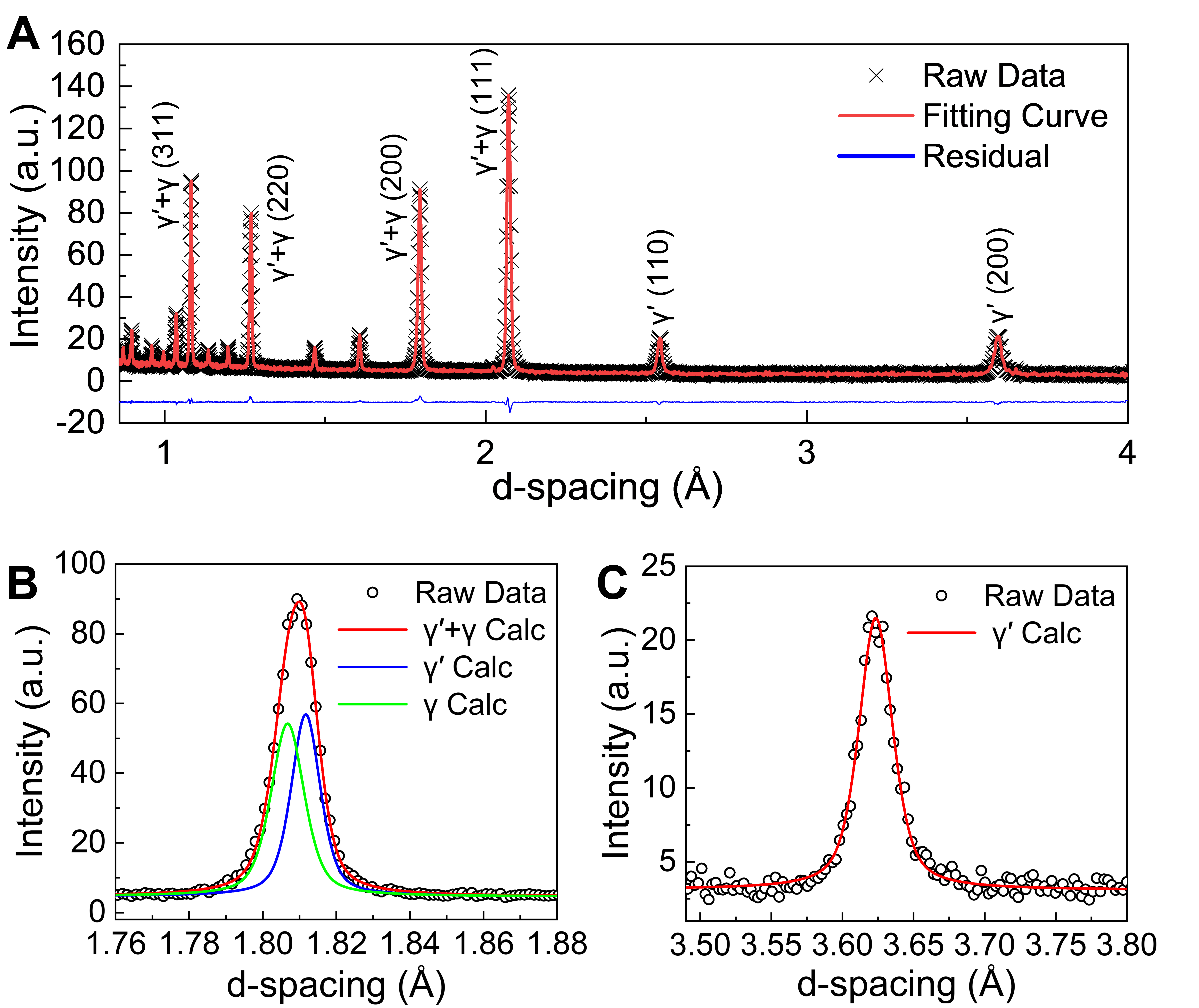
The diffraction patterns of the undeformed sample were subjected to Rietveld refinement using the
RESULTS AND DISCUSSION
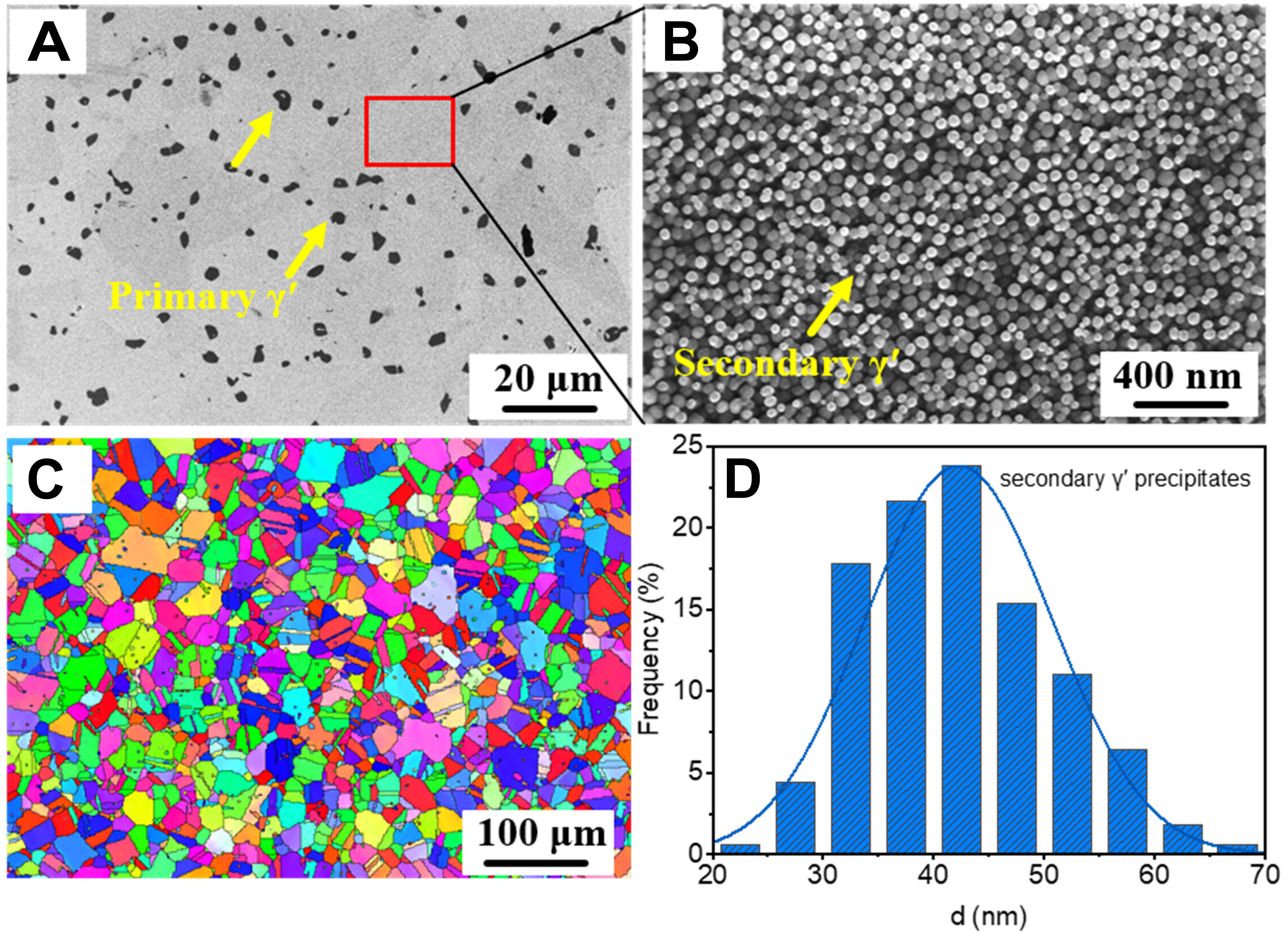
Figure 2 illustrates the bimodal size distribution of γ′ phases in the heat-treated (HT) alloy, characterized by the presence of primary γ′ phases with an average size of 1-3 μm, which are unevenly distributed near grain boundaries, and secondary γ′ phases with an average size of 44 nm that are uniformly dispersed throughout the matrix. The size of γ′ phases was quantified by measuring the equivalent circular diameter using Image Pro Plus software. Furthermore, the total volume fraction of γ′ phases was approximately 41%, as determined by Rietveld refinement of neutron diffraction patterns from the undeformed sample. The volume fraction of primary γ′ phases was calculated to be 3% based on the stereological principle of areal fraction equivalence, indicating that secondary γ′ phases contribute approximately 38%. The average grain size of the alloy is around 18 μm and no distinct preferred orientation was detected.
Figure 2. Microstructures of the HT specimen. (A) and (B) show the morphologies of primary and secondary γ′ phases, respectively; (C) The EBSD inverse pole figure (IPF) of the HT alloy; (D) The frequency distribution of secondary γ′ phases. HT: Heat-treated; EBSD: electron backscattered diffraction.
Intergranular strain response
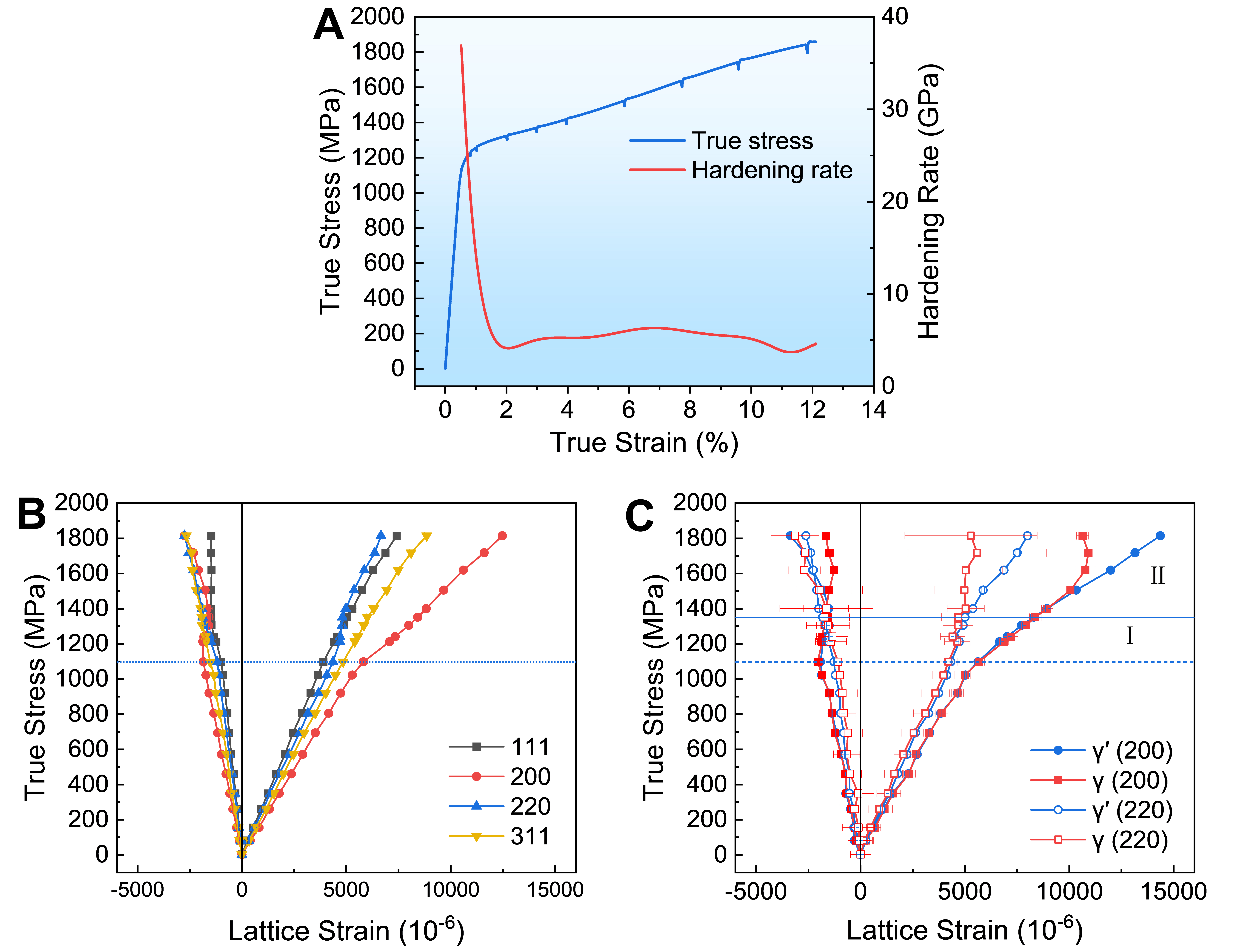
Figure 3A represents the true stress-strain curve and its corresponding work hardening rate profile obtained from in situ neutron tensile test. The alloy exhibits a proportional limit σp of approximately 1,038 MPa, a 0.2% offset yield strength (σ0.2) of 1,211 MPa, and an ultimate tensile strength of 1,860 MPa. The work hardening rate demonstrates a three-stage trend characterized by an initial decline, a slight increase, and a subsequent reduction. The peak value is observed at approximately 7% strain, which will be elaborated upon in subsequent sections. Note that the “jagged” line with stress relaxation during the plastic stage is just experimental-related rather than physical, which was caused by the temporary dwells in the displacement mode of the tensile test for acquiring the diffraction spectrum.
Figure 3. (A) True stress-strain curve and its corresponding work hardening rate curve of in situ neutron diffraction tensile test; (B) The intergranular lattice strains of alloy for the composite γ + γ′ overlapping FCC peaks; (C) The deconvoluted intragranular (interphase) lattice strains of individual phase in the {200} and {220} reflections. FCC: Face-centered cubic.
Intergranular strains of grains with different orientations are shown in Figure 3B. It is generally agreed that intergranular strains in polycrystals originate from the elastic and plastic anisotropy of differently oriented grains[34]. During the elastic deformation stage, different specific {hkl} grains along the loading direction (LD) exhibit various elastic strains, but all of which vary linearly with applied stress. The {111} grains exhibit the greatest stiffness and thus the highest elastic modulus, whereas the {200} grains are the most compliant and display the largest elastic lattice strain under equivalent stress. The stiffness of other {hkl} grains is intermediate between these two extremes. This orientation-dependent elastic strain can be predicted by the cubic elastic anisotropic factor Ahkl[37]. Moreover, the lattice strains along the transverse direction (TD) decrease with stress due to Poisson’s effect. A distinct transition point is observed when the applied stress exceeds 1,097 MPa, where the lattice strains of the {200}, {111}, and {220} grains begin to show a linear deviation, indicating the onset of micro-yielding anisotropy. As the applied stress further increases to
Grains with orientations exhibiting a lower strength-to-stiffness ratio are expected to yield earlier than those with a higher ratio. The lattice strains and load transfer that depend on orientation among various {hkl} grains can be accounted for by the elastic anisotropic factor Ahkl and the Schmid factor m. According to the Voigt model, a greater value of Ahkl corresponds to increased stiffness. In FCC structures, the anisotropic factors for different {hkl} grains are ranked as follows: A111 > A220 > A311 > A200 (A111 = 0.33, A220 = 0.25, A220 = 0.16, A200 = 0.00), indicating that E111 > E220 > E311 > E200. Furthermore, a higher Schmid factor associated with “soft” orientations suggests a greater maximum resolved shear stress ( τ = mσ = cosλ cosϕ σ) under loading, where λ represents the angle between the tensile direction and the normal to the slip plane, and ϕ denotes the angle between the tensile direction and the slip direction. The maximum Schmid factors of differently oriented grains for the FCC {111} < 110 > slip system are approximately m111 = 0.272 (6), m200 = 0.408 (8),
Interphase strain response
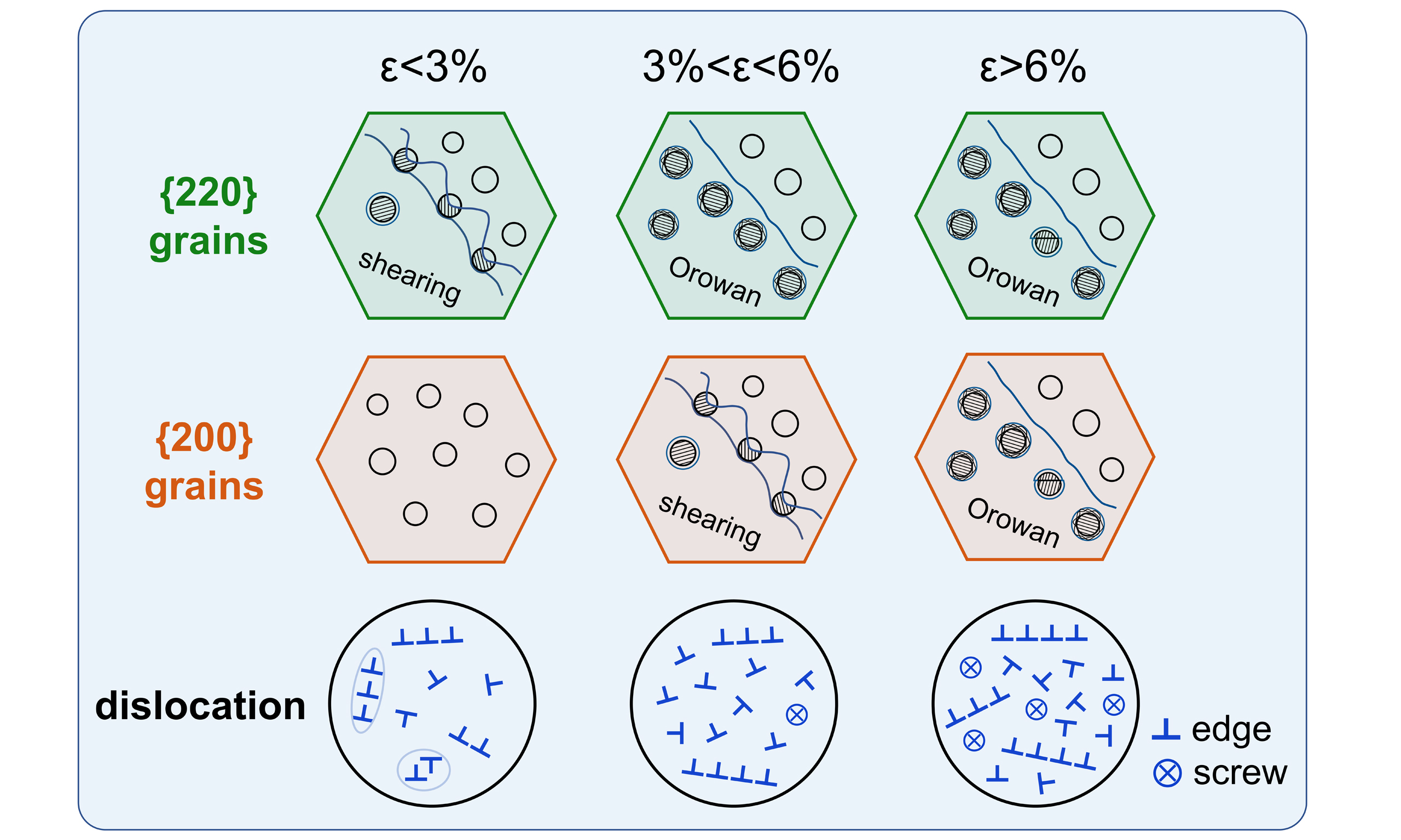
Figure 3C illustrates the evolution of the interphase strain in γ and γ′ phases within the {220} and {200} grains. During elastic deformation, the lattice strains of these two phases nearly coincide in both oriented grains. In the initial stage of plastic deformation, referred to as Stage I, the local phase strains of two phases in {220} and {200} grains still exhibit similar responses, indicating that the γ and γ′ phases are simultaneously sheared by dislocations and no interphase load transfer occurs. When the applied stress exceeds 1,351 MPa (~3% strain), denoted as Stage II, lattice strain separation first appears in the {220} oriented grains, accompanied by load transfer from γ to γ′. A similar load redistribution in the {200} grains is observed at the stress level of 1505 MPa (~6% strain). This asynchronism in interphase load transfer can be ascribed to plastic anisotropy, as shown in Figure 3B, which indicates that {220} grains yield prior to {200} grains. The sequential deformation mechanism is characterized by initial γ/γ′ co-deformation without load transfer during the early plastic stages, followed by deformation that concentrates in the γ phase and is accompanied by load transfer from γ to γ′ at higher strains. TEM analysis of dislocation configurations provides conclusive evidence for identifying γ′ phase deformation behavior.
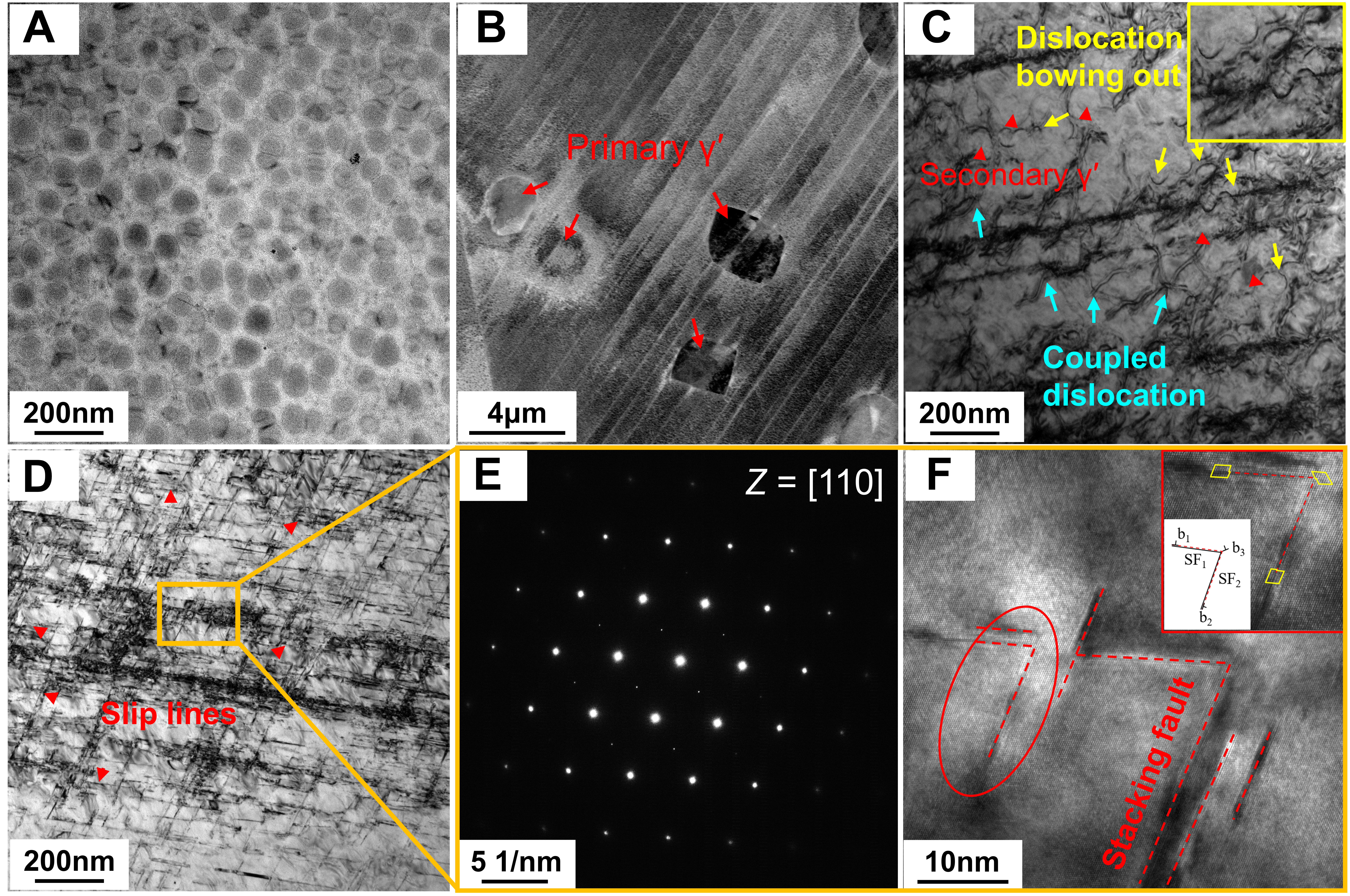
Figure 4 compares the microstructural characteristics between undeformed and 10%-strained samples through ECCI and TEM imaging. The undeformed specimen in Figure 4A displays uniformly distributed secondary γ′ phases and only a few dislocations. Numerous parallel slip bands in Figure 4B and C indicate planar slip as the predominant mode of dislocation motion. Furthermore, Figure 4C illustrates the presence of dislocation pairs that shear secondary γ′ phases, with dislocation spacing and precipitate size confirming strongly coupled interactions. These findings are consistent with the γ/γ′ co-deformation behavior identified by neutron diffraction. In addition, pronounced dislocation bowing around γ′ phases in Figure 4C implies the concurrent operation of Orowan looping. The linear features in Figure 4D were carefully examined through selected area electron diffraction (SAED) and high-resolution TEM (HR-TEM) imaging. The SAED pattern in Figure 4E exhibits no stacking fault streaking, although stacking faults with characteristic V-type Lomer-Cottrell locks[15] are observed in Figure 4F. This finding indicates limited stacking fault density throughout the deformed microstructure. These linear features therefore correspond to short slip traces rather than stacking fault ribbons, as established in previous studies[18,22], and they are frequently interrupted or deflected near non-shearable γ′ phases, confirming Orowan mechanism dominance during high-strain deformation. The microstructural observations lead to two critical findings: First, planar slip dominates dislocation motion in the Ni-Co-based superalloy, as a consequence of the decreased stacking fault energy induced by substantial Co additions (> 20%). Second, γ′ phases undergo both shearing and Orowan looping deformation throughout plastic deformation. When considered together with the evolution of lattice strain, these results highlight the mechanism transition from shearing dominance to Orowan bypassing dominance as deformation proceeds.
Figure 4. Substructures of undeformed and 10%-strained alloys. (A) BF-TEM image of undeformed specimen; (B) ECCI, (C and D)
Several studies have demonstrated that the bimodal size distribution of γ′ could be used to explain the combination of shearing and looping mechanisms[39,40]. However, such combined behavior is not typically observed in alloys containing excessively coarse, low-volume-fraction primary phases when coupled with a homogeneous distribution of secondary phases. Additionally, Jaladurgam et al.[19] argued that this behavior depends on the critical stress for looping, which is related to the particle size (γ′ volume fraction) in the alloy. Moreover, extra work hardening during co-deformation is required to achieve a higher critical looping stress when a high volume fraction of the γ′ phase is present[18,25]. During initial deformation, some γ′ precipitates deform by the shearing mechanism, whereas larger particles undergo deformation via Orowan looping. Notably, synchronous lattice strain evolution in both phases, along with established relationships reported in prior studies, demonstrates that dislocation pair shearing acts as the primary deformation mode for secondary γ′ precipitates during the early stages. As deformation progresses, shearing of the γ′ phase becomes unfavorable and is gradually replaced by Orowan looping as the predominant mechanism. Two possible factors contribute to this transition: (a) According to Zhang et al.[4] and McAllister et al.[41], residual dislocations generated from initial looping or shearing accumulate around precipitates, impeding subsequent dislocations from shearing into the γ′ phase and thereby promoting the Orowan mechanism; (b) The γ′ phase exhibits distinct hardening behavior compared to the matrix, often attributed to dislocations being locked within the γ′ phase due to cross-slip on the {100} slip plane, which inhibits further shearing and activates Orowan looping[17]. Nevertheless, the combination of low stacking fault energy and deformation at room temperature makes cross-slip in the current alloy difficult. Consequently, pile-up around the γ′ phase is the primary cause for the mechanism transition from shearing to Orowan looping. As a result, the load transfer from the γ matrix to the γ′ phase becomes increasingly significant with the predominance of the looping mechanism. One has to bear in mind that even when Orowan looping is dominant, stress concentrations from dislocation accumulation can intermittently force shearing of some γ′ particles, as dislocation pile-ups may overcome back stresses under localized high-stress conditions[18,42].
Dislocation structures from CMWP analysis
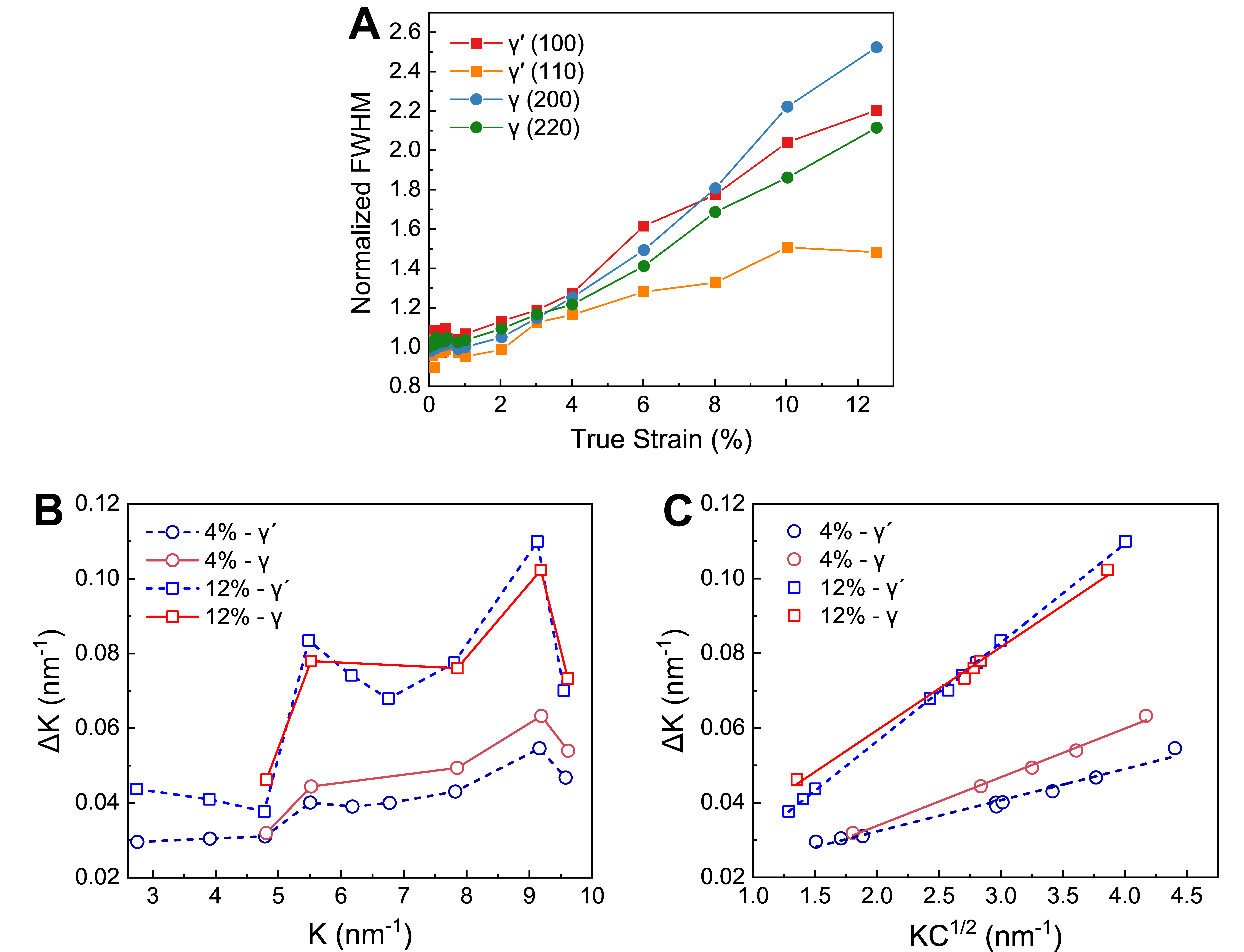
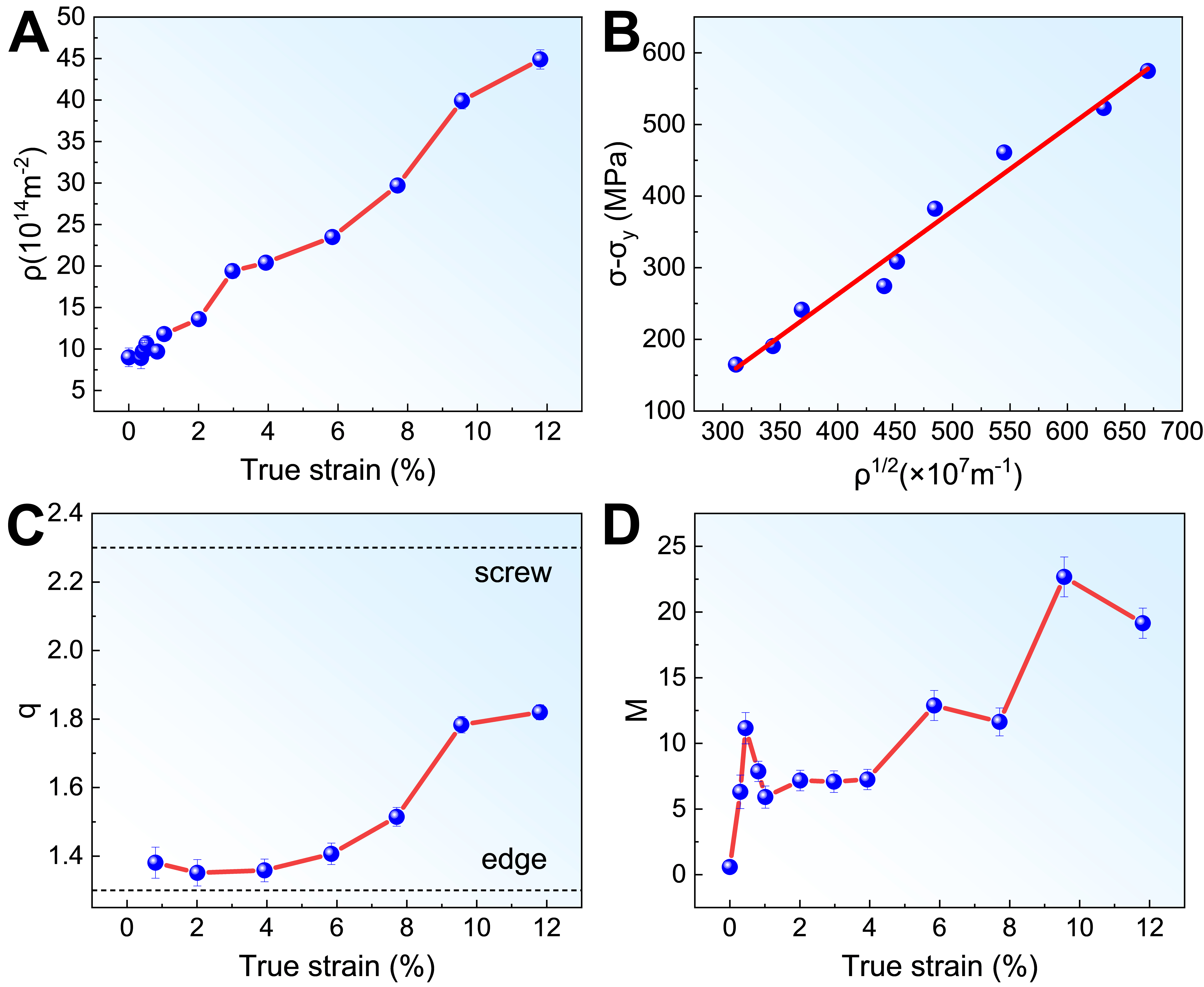
The evolution of the full width at half maximum (FWHM) of the reflection peak can be utilized to demonstrate the crystallite size and the inhomogeneous stress field caused by crystal defects such as dislocations during deformation. As depicted in Figure 5A, the normalized FWHM relative to the undeformed state for both γ and γ′ reflections along the loading direction exhibits a continuous increase with tensile strain, indicating active dislocation multiplication. The conventional Williamson-Hall (cWH) plot presented in Figure 5B shows significant scatter attributed to the pronounced anisotropy of peak broadening, which decreases the accuracy of the dislocation density derived from the slope. After introducing the average contrast factor, the modified Williamson-Hall (mWH) diagram in Figure 5C exhibits markedly improved linearity; the larger slope at 12% strain relative to 4% strain qualitatively confirms a higher dislocation density as deformation proceeds. The similar trend observed for the γ/γ′ reflections indicates that the precipitates also experience substantial plastic deformation, consistent with previous results. Nevertheless, it is important to note that mWH still relies on simplified strain/size models and provides only semi-quantitative estimates, and the CMWP fitting routine was subsequently performed to derive quantitatively reliable dislocation densities, as well as insights into dislocation character and spatial arrangement. As depicted in Figure 6A, the γ + γ′ total average dislocation density increased uniformly from 8.0 × 10¹⁴ m-2 to 4.5 × 10¹⁵ m-2 in response to varying strain levels. Furthermore, the increment in flow stress
Figure 5. The neutron diffraction peak profile analysis. (A) The evolution of normalized FWHM as a function of true strain; (B) The cWH plots at true strains of 4% and 12%, respectively; (C) The mWH plots at true strains of 4% and 12%, respectively. The parameter K (1/d) is the diffraction vector, and C is the average contrast factor. FWHM: Full width at half maximum; cWH: conventional
Figure 6. The CMWP fitting results of the Ni-Co-based superalloy. (A) The evolution of total average dislocation density (ρ) with true strain; (B) The flow stress increase (σ - σy) with strain as a function of ρ1/2; (C) The dislocation character factor q with true strain; (D) The dislocation configuration parameter M with true strain.
The parameter q reflects the dislocation character and the elastic anisotropy of materials. The q values of approximately 1.3 and 2.3 were estimated for the pure edge- and pure screw-type dislocations in superalloys, respectively[43]. Figure 6C demonstrates that the q value gradually rises with increasing strain, showing the increased proportion of screw dislocations in the Ni-Co-based superalloy during plastic deformation. Actually, the distortion energy generated by screw dislocations of the same length is only 1/3 of that of edge dislocations. As the dislocation density increases, the proportion of low-energy screw dislocations inevitably increases to reduce the system energy and enhance dislocation mobility. In high-SFE metals with wavy slip characteristics, screw dislocations with opposite Burgers vectors will annihilate through cross slip, thereby reducing the proportion of screw dislocations and the q value. This phenomenon has also been confirmed in the lath martensitic steel[28]. In contrast, the low stacking fault energy characteristics of the Ni-Co-based superalloy studied significantly suppress the cross slip and dislocation motion is restricted within the two-dimensional slip plane, ultimately manifesting as an increase in q value. The evolution of dislocation types above provides new evidence that the dislocation motion in the
The parameter M, which is the product of the effective cut-off radius of dislocation (Re) and the square root of dislocation density (ρ), i.e., M = Re × ρ1/2, provides a quantitative evaluation of the dislocation arrangement characteristics. A small M value (M < 1) indicates a strong interaction between dislocations, where their long-range stress fields are effectively screened, leading to the formation of low-energy dislocation structures such as dipoles, multipoles, dislocation walls and cells. Conversely, a large M value
The rising M value observed in the current alloy thus suggests a fundamental deviation from the expected energy-minimizing behavior. It is proposed that the presence of γ′ precipitates, which are characteristic of superalloy systems, fundamentally alters the pathway of dislocation structure evolution.
It is well established that precipitate size determines the deformation mechanism, with a transition from shearing for small particles to Orowan looping for larger ones. This transition can be anticipated to not only impact the microscopic mechanical behavior but also significantly influence the organization of dislocations; however, a comprehensive understanding of this phenomenon has yet to be achieved. Further systematic investigations that correlate precipitate characteristics such as size and spacing with the evolution of the dislocation configuration are essential for developing a comprehensive and predictive model for work hardening in advanced precipitation-strengthened superalloys.
Evolution of work hardening rate
The work hardening rate, illustrated in Figure 3A, demonstrates a distinctive three-stage behavior that had also been reported by Grant et al.[18]. In Stage I, where strain is less than 2%, the initial sharp decline in the hardening rate is governed by the shearing of γ′ precipitates through dislocation pairs. The γ′ shearing promotes strain localization, and the dislocation density in the alloy remains low at this stage. Consequently, the alloy exhibits weak work hardening. In Stage II, as strain increases from 2% to 7%, the hardening rate exhibits a significant increase. This rise is attributed to a gradual transition from the shearing-dominated mechanism to Orowan bypassing dominance, a shift corroborated by in situ neutron diffraction data. The onset of lattice strain separation between the γ and γ′ phases in the most compliant {200} grain family at approximately 6% strain, as shown in Figure 3C, indicates global activation of Orowan looping. This is accompanied by a significant increase in the q value from CMWP analysis, a direct result of the accumulation of Orowan loops. Orowan looping acts as a potent hardening mechanism, as the remnant loops create a dense, tangled substructure that severely impedes dislocation motion and thus causes stronger work hardening. In Stage III, when strain exceeds 7%, the observed decline in the hardening rate is attributed to localized dislocation reorganization rather than to extensive dynamic recovery. The accumulation of Orowan loops surrounding γ′ phases leads to pronounced local stress concentrations, compelling screw dislocation segments to undertake stress-assisted yet limited cross-slip. As a result, these screw dislocations experience only localized rearrangement and are extensively annihilated or reorganized into lower-energy structures, as evidenced by the continual rise in dislocation density and the M value. Importantly, this localized cross-slip allows screw dislocations to bypass high-density obstacle regions such as Orowan loop clusters by transferring to adjacent slip planes, thereby reducing local slip resistance and ultimately manifesting as a decrease in the work hardening rate. Throughout the entire deformation, concurrent grain rotation occurs to accommodate plastic strain. Although such rotation induces a “geometrical softening” effect by aligning grains to enable easier slip, it simultaneously generates a high density of geometrically necessary dislocations, leading to a dominant hardening contribution. However, this hardening cannot fully explain the three-stage fluctuation observed in the work hardening rate, which is fundamentally governed by the interaction between dislocations and γ′ precipitates.
CONCLUSIONS
In this work, in situ neutron diffraction measurements were adopted to quantitatively examine the micromechanical behavior and the evolution of dislocation structures of a Ni-Co-based superalloy during tensile deformation. The primary conclusions are as follows:
(1) The γ and γ′ phases undergo co-deformation via dislocation shearing in the initial plastic stage, followed by the activation of the Orowan mechanism at higher strain levels, which accounts for the load transfer from the γ to γ′ phase.
(2) The low stacking fault energy suppresses cross-slip, leading to a rising fraction of screw-type dislocations. Critically, the pinning effect of γ′ precipitates impedes the self-organization of these dislocations into low-energy configurations, promoting the formation of high-energy, weakly screened structures.
(3) The evolution of work hardening is closely linked to these mechanisms. The late-stage decrease in the work hardening rate is attributed to the activation of localized, restricted cross-slip, which allows dislocations to bypass the high-density obstacle regions created by Orowan loops and accumulated dislocations around precipitates.
DECLARATIONS
Authors’ contributions
Data analysis, interpretation and writing of the draft: Liu, Y.; Yan, Z.; Gao, Y.; Li, Y.
Material, data acquisition, design of the study and interpretation: Yan, Z.; Gan, B.; Harjo, S.; Gong, W.; Kawasaki, T.
Data analysis and interpretation and contribution to the development of the article: Li, S.; Wang, Y. D.
Availability of data and materials
Data will be made available from the corresponding author upon reasonable request.
Financial support and sponsorship
This work was supported by the National Key Research and Development Program of China (No. 2021YFA1600600), the National Natural Science Foundation of China (NSFC) (No. U2141206, 51921001), the Fundamental Research Funds for the Central Universities (Grant Nos. FRF-TP-20-03C2, FRF-BD-20-02B), and the Guangdong-Hong Kong-Macao Joint Laboratory for Neutron Scattering Science and Technology. The neutron diffraction experiments were conducted on a time-of-flight neutron diffractometer TAKUMI (BL 19) at the Materials and Life Science Experimental Facility of J-PARC with the proposal of 2020B0421.
Conflicts of interest
Dr. Wang, Y. D. is an Associate Editor of the journal Microstructures. Dr. Wang, Y. D. was not involved in any steps of editorial processing, notably including reviewer selection, manuscript handling, or decision making. The other authors declared that there are no conflicts of interest.
Ethical approval and consent to participate
Not applicable.
Consent for publication
Not applicable.
Copyright
© The Author(s) 2025.
REFERENCES
1. Reed, R. C. The superalloys: fundamentals and applications, 1st ed.; Cambridge University Press, New York, 2006.
2. Williams, J. C.; Starke, E. A. Progress in structural materials for aerospace systems. Acta. Mater. 2003, 51, 5775-99.
3. Osada, T.; Gu, Y.; Nagashima, N.; Yuan, Y.; Yokokawa, T.; Harada, H. Optimum microstructure combination for maximizing tensile strength in a polycrystalline superalloy with a two-phase structure. Acta. Mater. 2013, 61, 1820-9.
4. Zhang, R.; Qin, H.; Bi, Z.; et al. γ′′ variant-sensitive deformation behaviour of Inconel 718 superalloy. J. Mater. Sci. Technol. 2022, 126, 169-81.
5. Gu, Y.; Cui, C.; Yuan, Y.; et al. Research progress in a high performance cast & wrought superalloy for turbine disc applications. Acta. Metall. Sin. 2015, 51, 1191-206.
6. Tian, C.; Han, G.; Cui, C.; Sun, X. Effects of Co content on tensile properties and deformation behaviors of Ni-based disk superalloys at different temperatures. Mater. Des. 2015, 88, 123-31.
7. Gu, Y. F.; Cui, C.; Harada, H.; et al. Development of Ni-Co base alloys for high-temperature disk applications. In Superalloys 2008 (Eleventh International Symposium), Champion, PA, USA, September 14-18, 2008; Reed, R. C.; Green, K. A, Caron, P.; Gabb, T. P.; Fahrmann, M. G.; Huron, E. S., Eds.; TMS: Warrendale, PA, 2008; pp 53-61.
8. Al-hammadi, R. A.; Zhang, R.; Cui, C.; Zhou, Z.; Zhou, Y. Effects of temperature on superplastic and fracture behaviors of a Ni-Co-based superalloy. J. Alloys. Compd. 2023, 958, 170524.
9. Gu, Y.; Harada, H.; Cui, C.; Ping, D.; Sato, A.; Fujioka, J. New Ni-Co-base disk superalloys with higher strength and creep resistance. Scr. Mater. 2006, 55, 815-8.
10. Yuan, Y.; Gu, Y.; Osada, T.; Zhong, Z.; Yokokawa, T.; Harada, H. A new method to strengthen turbine disc superalloys at service temperatures. Scr. Mater. 2012, 66, 884-9.
11. Vorontsov, V. A.; Mcauliffe, T. P.; Hardy, M. C.; Dye, D.; Bantounas, I. Precipitate dissolution during deformation induced twin thickening in a CoNi-base superalloy subject to creep. Acta. Mater. 2022, 232, 117936.
12. Li, Y.; Hong, Z.; Liu, B.; Jia, X. Investigation of microstructure evolution and mechanical properties of multi-precipitation Ni-Co base superalloys. Mater. Sci. Eng. A. 2021, 801, 140333.
13. Yang, C.; Hu, R.; Wang, X.; et al. Effect of pre-tensile treatments on the mechanical properties and deformation mechanism of a novel Ni-based superalloy. Mater. Sci. Eng. A. 2023, 874, 145063.
14. Ding, R.; Zhou, Q.; Qin, H.; et al. Effect of test temperature on deformation microstructure and tensile property of a novel Ni-Co-based superalloy. Mater. Sci. Eng. A. 2024, 915, 147269.
15. Qi, D.; Fu, B.; Du, K.; et al. Temperature effects on the transition from lomer-cottrell locks to deformation twinning in a Ni-Co-based superalloy. Scr. Mater. 2016, 125, 24-8.
16. Daymond, M.; Preuss, M.; Clausen, B. Evidence of variation in slip mode in a polycrystalline nickel-base superalloy with change in temperature from neutron diffraction strain measurements. Acta. Mater. 2007, 55, 3089-102.
17. Preuss, M.; da Fonseca, J. Q.; Grant, B.; et al. The effect of γ′ particle size on the deformation mechanism in an advanced polycrystalline nickel-base superalloy. In Superalloys 2008 (Eleventh International Symposium), Champion, PA, USA, September 14-18, 2008; Reed, R. C.; Green, K. A, Caron, P.; Gabb, T. P.; Fahrmann, M. G.; Huron, E. S., Eds.; TMS: Warrendale, PA, 2008; pp 405-14.
18. Grant, B. M.; Francis, E. M.; Quinta, da. Fonseca. J.; Daymond, M. R.; Preuss, M. Deformation behaviour of an advanced nickel-based superalloy studied by neutron diffraction and electron microscopy. Acta. Mater. 2012, 60, 6829-41.
19. Jaladurgam, N. R.; Li, H.; Kelleher, J.; Persson, C.; Steuwer, A.; Colliander, M. H. Microstructure-dependent deformation behaviour of a low γ′ volume fraction Ni-base superalloy studied by in-situ neutron diffraction. Acta. Mater. 2020, 183, 182-95.
20. Goodfellow, A.; Kelleher, J.; Jones, N.; Dye, D.; Hardy, M.; Stone, H. The effect of Mo on load partitioning and microstrain evolution during compression of a series of polycrystalline Ni-Based superalloys. Acta. Mater. 2019, 176, 318-29.
21. Huang, S.; Gao, Y.; An, K.; et al. Deformation mechanisms in a precipitation-strengthened ferritic superalloy revealed by in situ neutron diffraction studies at elevated temperatures. Acta. Mater. 2015, 83, 137-48.
22. Yang, J.; Li, H.; Gao, T.; et al. Deformation behavior of nickel-based superalloys with bimodal γ′ size distribution studied by in-situ neutron diffraction combined with EVPSC modeling. J. Alloys. Compd. 2024, 977, 173382.
23. Gao, Y.; Ding, Y.; Li, H.; et al. Grain-size dependent elastic-plastic deformation behaviour of inconel 625 alloy studied by in-situ neutron diffraction. Intermetallics 2021, 138, 107340.
24. Jaladurgam, N. R.; Kabra, S.; Colliander, M. H. Macro- and micro-mechanical behaviour of a γ′ strengthened Ni-based superalloy at cryogenic temperatures. Mater. Des. 2021, 209, 109954.
25. Francis, E.; Grant, B.; Fonseca, J. Q. D.; et al. High-temperature deformation mechanisms in a polycrystalline nickel-base superalloy studied by neutron diffraction and electron microscopy. Acta. Mater. 2014, 74, 18-29.
26. Ungár, T.; Gubicza, J.; Ribárik, G.; Borbély, A. Crystallite size distribution and dislocation structure determined by diffraction profile analysis: principles and practical application to cubic and hexagonal crystals. J. Appl. Crystallogr. 2001, 34, 298-310.
27. Ribárik, G.; Ungár, T.; Gubicza, J.
28. Harjo, S.; Kawasaki, T.; Tomota, Y.; et al. Work hardening, dislocation structure, and load partitioning in lath martensite determined by in situ neutron diffraction line profile analysis. Metall. Mater. Trans. A. 2017, 48, 4080-92.
29. Akama, D.; Tsuchiyama, T.; Takaki, S. Change in dislocation characteristics with cold working in ultralow-carbon martensitic Steel. ISIJ. Int. 2016, 56, 1675-80.
30. Gubicza, J.; Máthis, K.; Nagy, P.; et al. In-situ study of the microstructure evolution during tension of a Mg-Y-Zn-Al alloy processed by rapidly solidified ribbon consolidation technique. J. Magnes. Alloys. 2024, 12, 2024-40.
31. Ying, H.; Yang, X.; He, H.; et al. Anomalous dislocation response to deformation strain in CrFeCoNiPd high-entropy alloys with nanoscale chemical fluctuations. Scr. Mater. 2024, 250, 116181.
32. Xiao, Z.; He, J.; Gu, J.; et al. Tensile properties and deformation mechanisms of a new Ni-Co base superalloy from room temperature up to 750 °C. Intermetallics 2022, 150, 107697.
33. Oishi, R.; Yonemura, M.; Nishimaki, Y.; et al. Rietveld analysis software for J-PARC. Nucl. Instrum. Methods. Phys. Res. Sect. A. 2009, 600, 94-6.
34. Coakley, J.; Dye, D. Lattice strain evolution in a high volume fraction polycrystal nickel superalloy. Scr. Mater. 2012, 67, 435-8.
35. Ungár, T.; Holden, T. M.; Jóni, B.; et al. Dislocation structure in different texture components determined by neutron diffraction line profile analysis in a highly textured Zircaloy-2 rolled plate. J. Appl. Crystallogr. 2015, 48, 409-17.
36. Ribárik, G.; Jóni, B.; Ungár, T. The convolutional multiple whole profile (CMWP) fitting method, a global optimization procedure for microstructure determination. Crystals 2020, 10, 623.
37. Blondé, R.; Jimenez-melero, E.; Zhao, L.; et al. High-energy X-ray diffraction study on the temperature-dependent mechanical stability of retained austenite in low-alloyed TRIP steels. Acta. Mater. 2012, 60, 565-77.
38. Ma, S.; Rangaswamy, P.; Majumdar, B. Microstress evolution during in situ loading of a superalloy containing high volume fraction of γ′ phase. Scr. Mater. 2003, 48, 525-30.
39. Dye, D.; Stone, H.; Reed, R. A two phase elastic-plastic self-consistent model for the accumulation of microstrains in Waspaloy. Acta. Mater. 2001, 49, 1271-83.
40. Stone, H.; Holden, T.; Reed, R. On the generation of microstrains during the plastic deformation of Waspaloy. Acta. Mater. 1999, 47, 4435-48.
41. Mcallister, D.; Lv, D.; Peterson, B.; Deutchman, H.; Wang, Y.; Mills, M. Lower temperature deformation mechanisms in a γ′′-strengthened Ni-base superalloy. Scr. Mater. 2016, 115, 108-12.
42. Jackson, M.; Reed, R. Heat treatment of UDIMET 720Li: the effect of microstructure on properties. Mater. Sci. Eng. A. 1999, 259, 85-97.
43. Ungár, T.; Dragomir, I.; Révész, Á.; Borbély, A. The contrast factors of dislocations in cubic crystals: the dislocation model of strain anisotropy in practice. J. Appl. Crystallogr. 1999, 32, 992-1002.
44. Borbély, A.; Ungár, T. X-ray line profiles analysis of plastically deformed metals. Comptes. Rendus. Physique. 2012, 13, 293-306.
45. Ungár, T.; Ribárik, G.; Topping, M.; et al. Characterizing dislocation loops in irradiated polycrystalline Zr alloys by X-ray line profile analysis of powder diffraction patterns with satellites. J. Appl. Crystallogr. 2021, 54, 803-21.
46. Kuhlmann-wilsdorf, D. Theory of plastic deformation: - properties of low energy dislocation structures. Mater. Sci. Eng. A. 1989, 113, 1-41.
47. Kuhlmann-wilsdorf, D. Chapter 59 the LES theory of solid plasticity. Dislocations. Solids. , 2002;11, 211-342.
Cite This Article
How to Cite
Download Citation
Export Citation File:
Type of Import
Tips on Downloading Citation
Citation Manager File Format
Type of Import
Direct Import: When the Direct Import option is selected (the default state), a dialogue box will give you the option to Save or Open the downloaded citation data. Choosing Open will either launch your citation manager or give you a choice of applications with which to use the metadata. The Save option saves the file locally for later use.
Indirect Import: When the Indirect Import option is selected, the metadata is displayed and may be copied and pasted as needed.
About This Article
Special Topic
Copyright
Data & Comments
Data




Comments
Comments must be written in English. Spam, offensive content, impersonation, and private information will not be permitted. If any comment is reported and identified as inappropriate content by OAE staff, the comment will be removed without notice. If you have any queries or need any help, please contact us at support@oaepublish.com.