


fig3
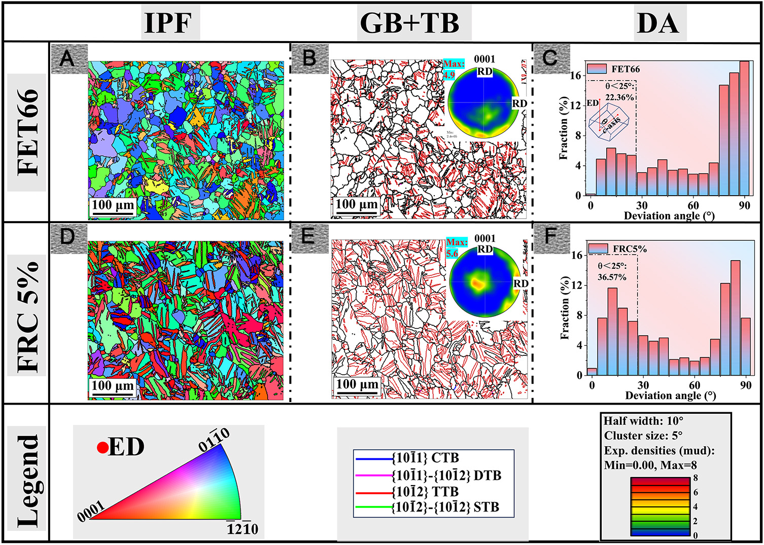
Figure 3. (A and D) IPF maps, (B and E) GB+TB maps and (C and F) DA maps of extruded AZ31 Mg alloy after (A-C) 66° FET and (D-F) 5 % FRC deformations. GB: Grain boundary; TB: twin boundary; IPF: inverse pole figure; FRC: free-rotational compression; FET: free end torsion; RD: rolling direction; ED: extrusion direction; TTB: tensile twin boundary; CTB: compressive twin boundary; STB: secondary twin boundary; DTB: double twin boundary.


