
fig1
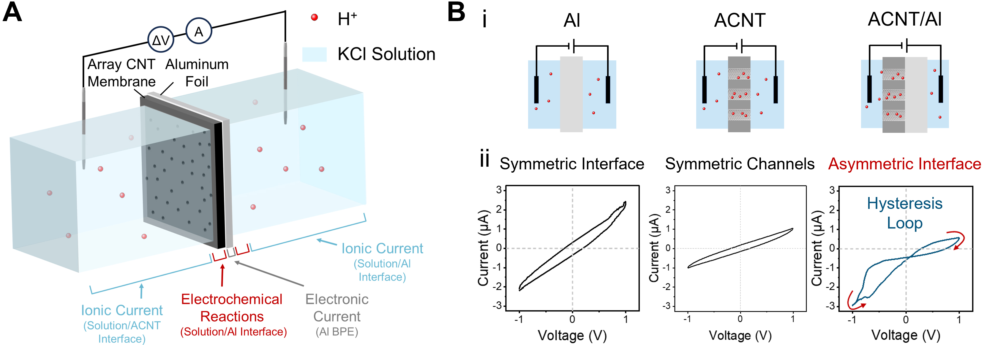
Figure 1. The ACNT/Al BPE iontronic memristor. (A) Schematic diagram of the installation and experimental setup of ACNT/Al, showing the internal current path; (B) (i) Simplified schematic diagrams of the Al, ACNT, and ACNT/Al systems and (ii) the corresponding I-V responses under a triangular potential waveform at an electrolyte concentration of 10 mM and a scan rate of 0.3 V/s. Both the electrochemical Al system and the nanofluidic ACNT system show symmetric, non-memristive I-V characteristics, whereas the asymmetric ACNT/Al BPE with coupling between electrochemical and nanofluidic processes exhibits a characteristic hysteresis loop typical of iontronic memristors. ACNT/Al: Al and CNT array-based aluminum; ACNT: a carbon nanotube array; Al: aluminum; CNT: carbon nanotube; BPE: bipolar electrode; I-V: current-voltage.

