



fig1
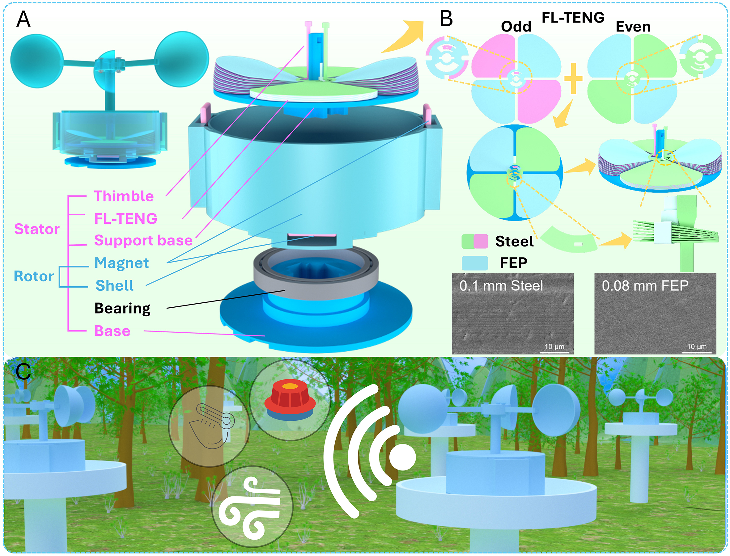
Figure 1. Structure of the FL-TENG based on the magnetic force separation principle. (A) Overall appearance and exploded schematic diagram of the device structure (the shell was designed with four magnet mounting positions: two on the side wall and two at the bottom, allowing flexible configuration for different experimental tests). (B) partial unit structure and material characterization of the FL-TENG. (C) schematic diagram of the application concept of the FL-TENG.