


fig5
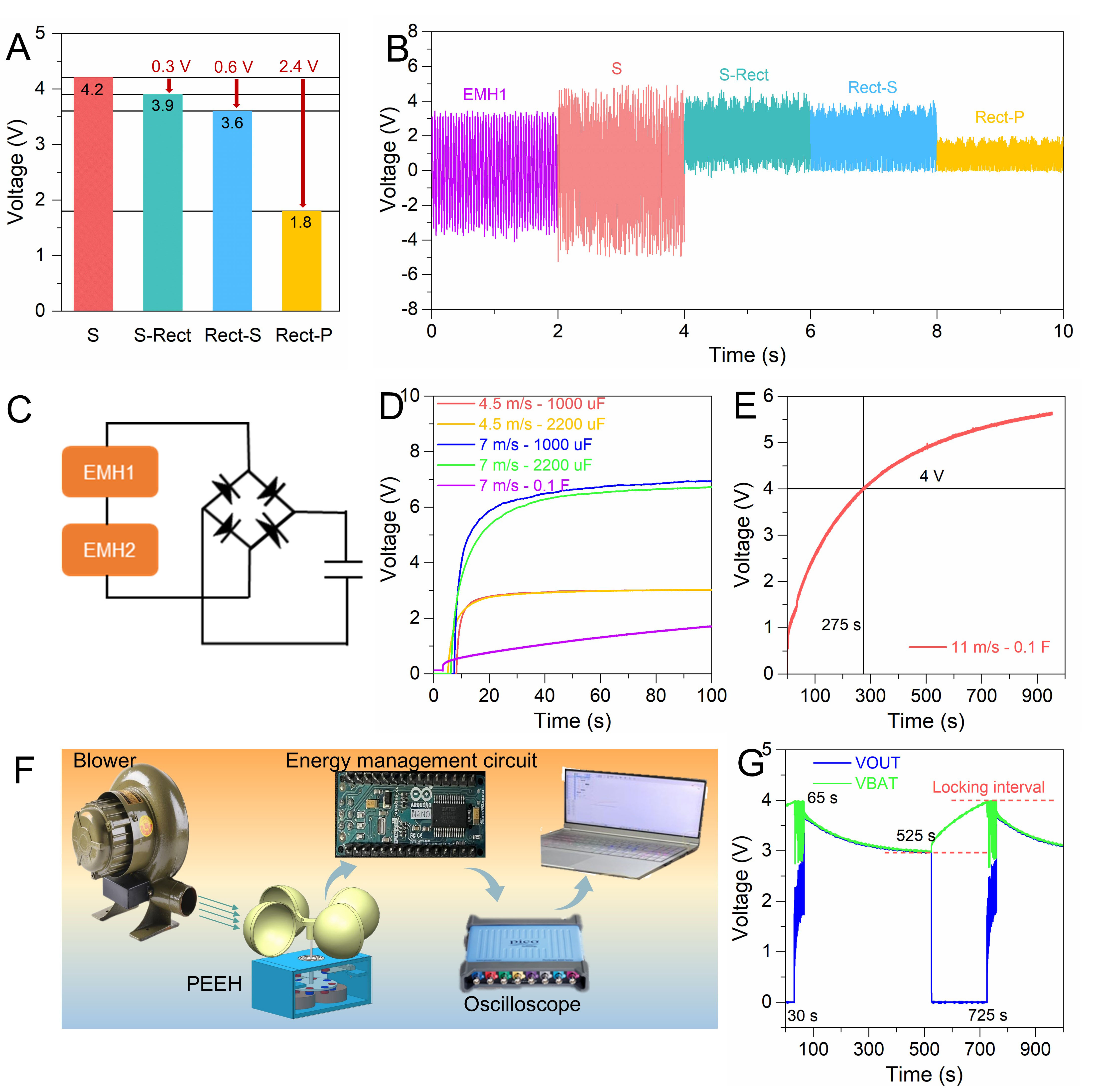
Figure 5. (A amd B) Outputs of EMH1 and EMH2 with different connections to the rectifier circuit (S: denotes the output voltage of the two coils in series, S-Rect: denotes the output voltage of the two coils in series and then rectified, Rect-S: means it first goes through a rectifier circuit to convert to DC output, and then combines in a series connection structure, and Rect-P denotes the output voltage of the two coils rectified and then in parallel), (C) Rectifier module circuit diagram, (D) Charging curves of PEEH for different capacitors, (E) Charging curves of PEEH for 0.1 F supercapacitor at 11 m/s wind speed, (F) energy management circuit test, (G) Circuit output test at 11 m/s wind speed.