fig9

Layered oxide cathodes for potassium-ion batteries: challenges, strategies and perspectives

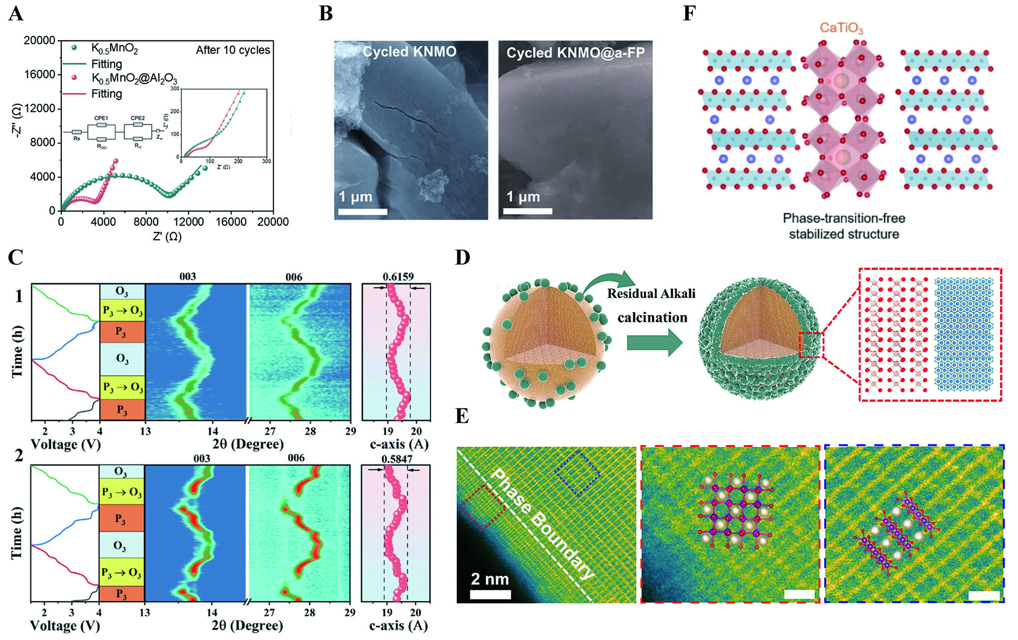
Figure 9. (A) Nyquist plots with the insets of high-frequency semicircles and corresponding equivalent circuits of K0.5MnO2 and K0.5MnO2@Al2O3 after 10 cycles[73]. Reprinted with permission from Ref.[73]. Copyright 2023 Elsevier.[73] (B) SEM images of the cycled electrodes[74]. Reprinted with permission from Ref.[74]. Copyright 2023 Wiley-VCH[74]. In-situ XRD spectra of (C1) KMCF and (C2) KMCF-P0.1[118]. Reprinted with permission from Ref.[118]. Copyright 2024 Elsevier[118]. (D) the schematic diagram of the KMTO structure[119]. Reprinted with permission from Ref.[119]. Copyright 2024 Elsevier[119]. (E) HADDF-STEM image of W-KMFMCO, indicative of the phase boundary. Reprinted with permission from Ref.[62]. Copyright 2024 Wiley-VCH[62]. (F) The schematic illustration of phase-transition-free CaTiO3 stabilized KMTO[115]. Reprinted with permission from Ref.[115]. Copyright 2024 Springer Nature[115].

Energy Materials
ISSN 2770-5900 (Online)
Follow Us

Portico

All published articles are preserved here permanently:

https://www.portico.org/publishers/oae/

Portico

All published articles are preserved here permanently:

https://www.portico.org/publishers/oae/