

fig6
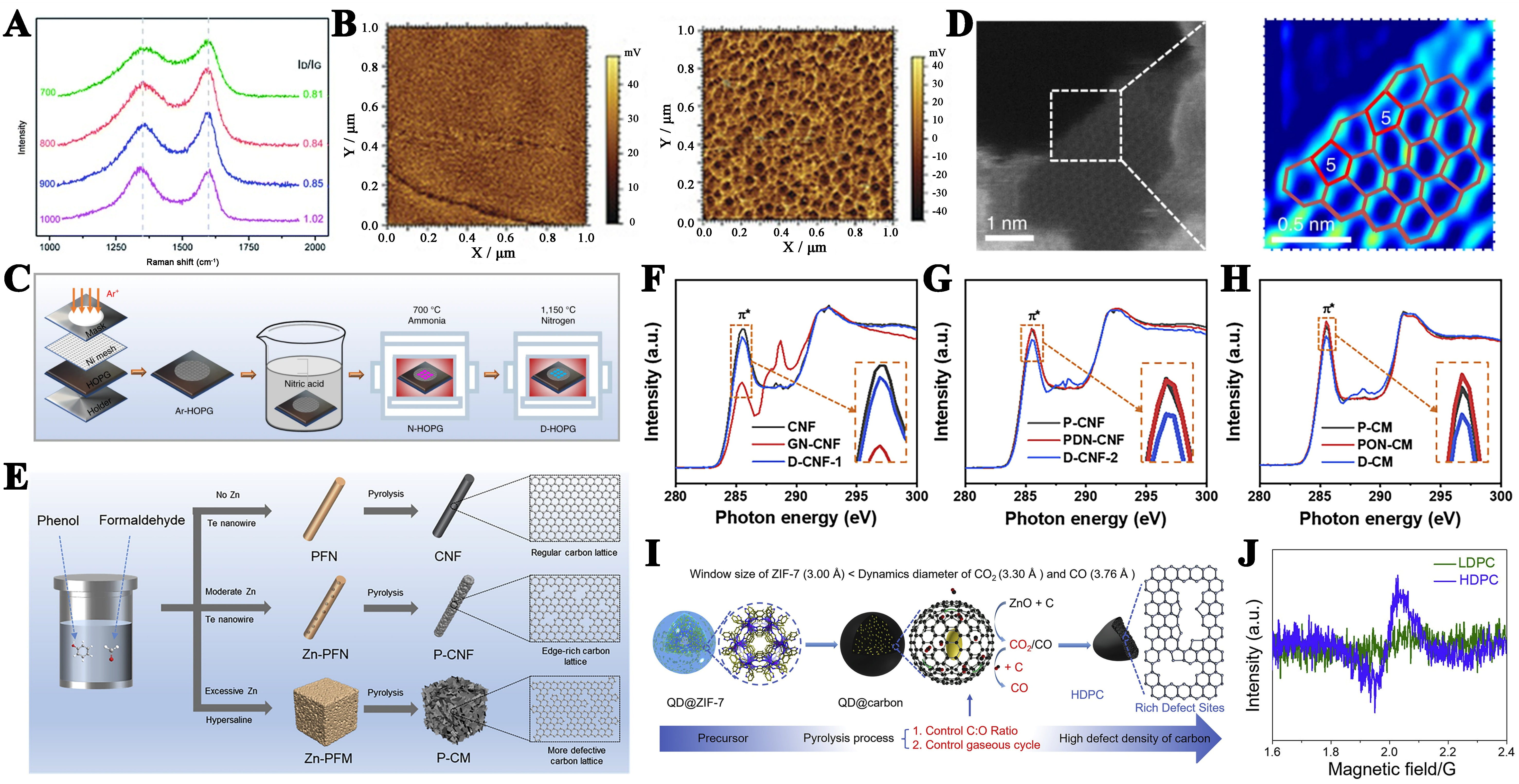
Figure 6. (A) Raman spectra of different types of catalysts. This figure is quoted with permission from Zhang et al.[159]; (B) KPFM test of HOPG before and after plasma etching. This figure is quoted with permission from Tao et al.[161]; (C) Synthetic scheme for the preparation of a D-HOPG sample; (D) The HAADF-STEM images derived from D-G [enlarged image of the dashed box in (D)]. This figure is quoted with permission from Jia et al.[162]; (E) Synthesis method of N-doped type carbon materials; (F-H) C K-edge XANES of different types CNF and CM. This figure is quoted with permission from Wang et al.[163]; (I) Schematic design and fabrication of HDPC; (J) EPR spectrum of LDPC and HDPC. This figure is quoted with permission from Wu et al.[165]. KPFM: Kelvin probe force microscopy; HOPG: highly oriented pyrolytic graphite; HAADF-STEM: high-angle annular dark field - scanning transmission electron microscopy; XANES: X-ray absorption near-edge structure; CNF: carbon nanofiber; CM: carbon monolith; EPR: electron paramagnetic resonance; LDPC: low density porous carbon; HDPC: high density porous carbon.


