

Self-limited atomic-layer tin-sulfides with high-electron-intensity interface induced ultrathin SEI for fast-charging sodium-ion batteries
 0
0 
Abstract
Fast-charging batteries that can be charged in minutes and store enough energy are highly desired in the electric vehicle and grid storage, but are usually limited to the electrodes with lower carrier diffusion. Herein, self-limited 1, 2, and 3 monolayers SnS2 on the graphene were fabricated as fast-charging anodes for sodium-ion batteries (SIBs). The tunable atomically-thin SnS2 compound was confirmed using synchrotron high-pressure powder X-ray diffraction, atomic force microscopy, and low-dose transmission electron microscopy (TEM). The 1, 2, and 3 atomic-layer SnS2 showed ultra-high phase contact of discharged products; thus, high bulk Na+/electronic conductivity was acquired. Simultaneously, ultra-thin and NaF, Na2CO3-riched solid-electrolyte interphase (6 nm, Cyro-TEM) was oriented construction in ester electrolyte. Benefiting from the synergistic effect of bulk phase and solid-electrolyte interphase, the obtained 3-monolayer SnS2 anode achieved a fast-charging capacity of 300 mAh·g-1 at 30 A·g-1 within 36 s, exhibiting new height of fast-charging ability in SIBs. Meanwhile, it demonstrated long-cycling stability with negligible capacity decay for 600 cycles. The assembled pouch cell with Na3V2(PO4)2F3 cathode showed a high-energy density of about 187.5 Wh·kg-1. The atomic-layer leveled regulation method paves the way for precise synthesis of materials at the atomic level and oriented design of fast-charging rechargeable batteries.
Keywords
INTRODUCTION
Fast-charging batteries with high energy density have recently received increased attention for electric vehicles[1-3]. However, due to the low ion conductivity of current electrode materials[4-6], batteries can only provide a limited energy density and typically require a relatively long charging time (hours or longer) for safe operation[7-9]. Now, sodium-ion batteries (SIBs) show great promise as a safer and cheaper alternative[10], and replacing conventional carbon-based anodes with high-capacity anodes is the most promising way to achieve fast-charging SIBs[11-13]. Conversion-type anodes, including SnS2, NiS, FeS2, and so on, are attractive because of their earth abundance and high theoretical capacities[14-16]. However, they still suffer from low Na+ conductivity and poor electronic properties with a thick solid-electrolyte interphase (SEI)[17-20]. Additionally, discharged products for the conversion reaction easily tend to aggregate, leading to low reaction reversibility[21-23]. These problems result in poor rate performance and rapid capacity degradation, which are the great challenges that impede practical applications[24-26].
To address these issues, diverse strategies have been developed to optimize electrochemical performance of conversion-type anodes via electrolytes and electrode engineering, respectively[27-30]. Ether-based electrolytes[31] are also developed to significantly improve electrochemical performance of conversion-type anodes because they are more resistant against reduction for the formation of stable and thin SEI[32,33]. However, their instability at high voltages, combined with high volatility and flammability, severely limits commercial development[34,35]. In addition, increasing the cut-off voltage can enhance reaction reversibility and cycling stability but suffer from low reversible capacity[36]. Furthermore, researchers have focused on increasing charge storage and transport properties by developing nano-architectures and/or adding conductive material[37]. Although notable progress has been made by these strategies, there is still a long way to go before achieving satisfactory results. Therefore, it is necessary to seek new approaches to improve electrochemical performance of conversion-type anodes.
Atomically thin materials have gained tremendous research interest for energy storage applications due to their unique electronic properties and highly exposed atoms, such as graphene, black P, transition metal dichalcogenides, and MXene, among others[38,39]. Ultra-thin layered structure can enable the rapid ionic diffusion, and enrich reaction site via abundant redox reaction near electrode surface[40-43], leading to a fast charge-discharge capability for sodium storage. Nevertheless, atomically thin materials thermodynamically tend to re-stack to form bulky agglomerates due to their high surface energy and are prone to particle pulverization during the cycling process[44,45].
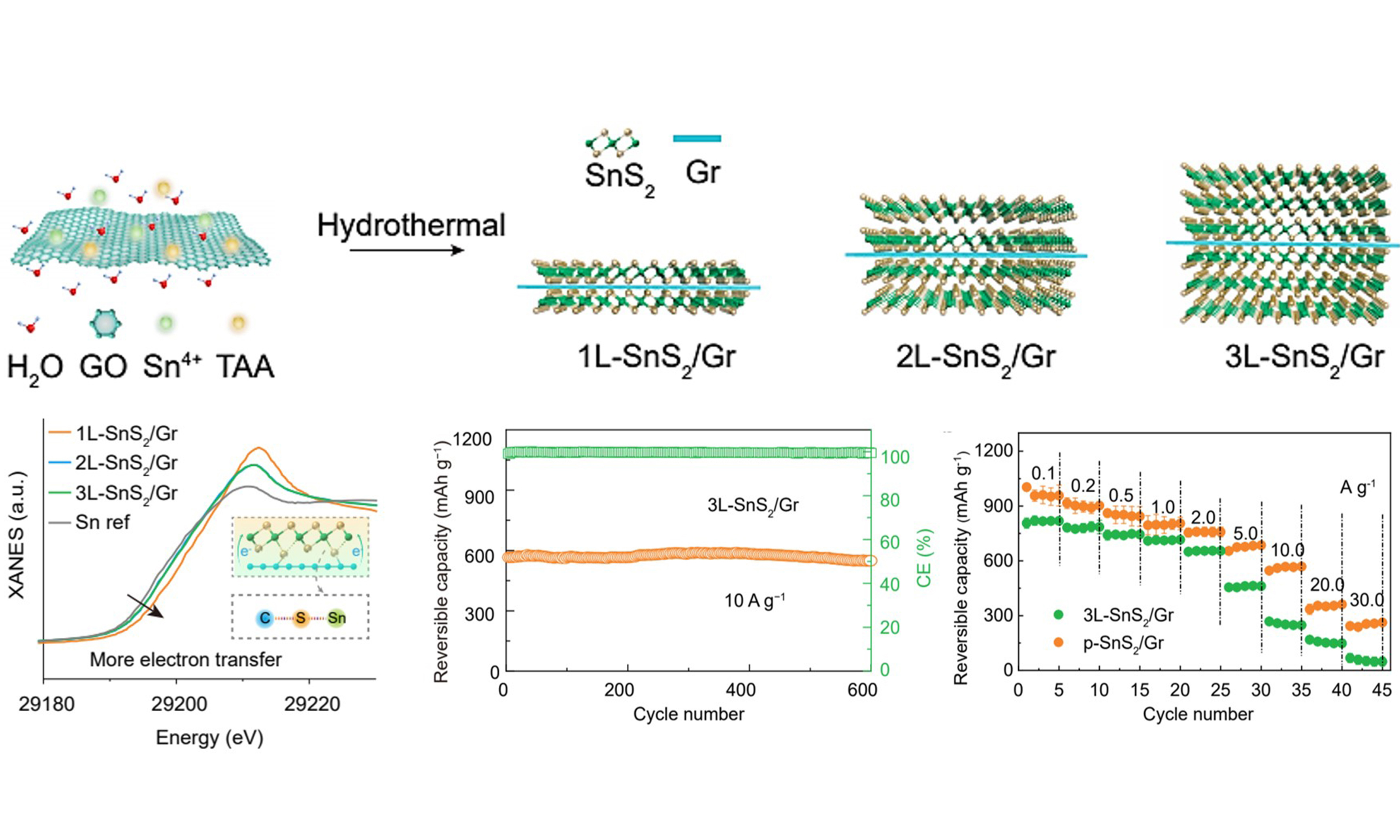
Herein, atomic-layer SnS2 is chemically coupled on the three-dimensional (3D) graphene via a self-limited growth process. Self-limited refers to the fact that SnS2 is preferentially adsorbed on the surface of graphene oxide (GO) to form new chemical bonds, resulting in the distortion of the lattice of materials and inhibiting its 3D growth, thus obtaining a two-dimensional (2D) structure[46]. In other words, oxygen-containing functional groups of GO surface can adsorb Sn4+ and then Sn4+ bound S2- to form SnS2. With the increasing content of Sn, 1L-SnS2/Gr, 2L-SnS2/Gr and 3L-SnS2/Gr grow on the surface of graphene in turn. Based on the construction of adsorption, a large area of uniform arrangement of up to three atomic layers can be formed. When the thickness of SnS2/Gr is increased by more than three layers, the adsorption function would fail to ensure the uniform arrangement of the atomic levels. Finally, 3L-SnS2/Gr with flake-like morphology and sandwich structure of composites can be obtained. Atomic-layer SnS2 with high electronic and ion conductivity not only enhances solid-phase interface contact of Sn and Na2S for high reversibility, but also induces an ultrathin SEI with tolerant interface compatibility for high reaction kinetics in the ester electrolyte [Scheme 1]. The obtained composite enables superior fast-charging capability, while possessing high-capacity retention after long cycles. The practical application is further verified in pouch cells with high-energy density.
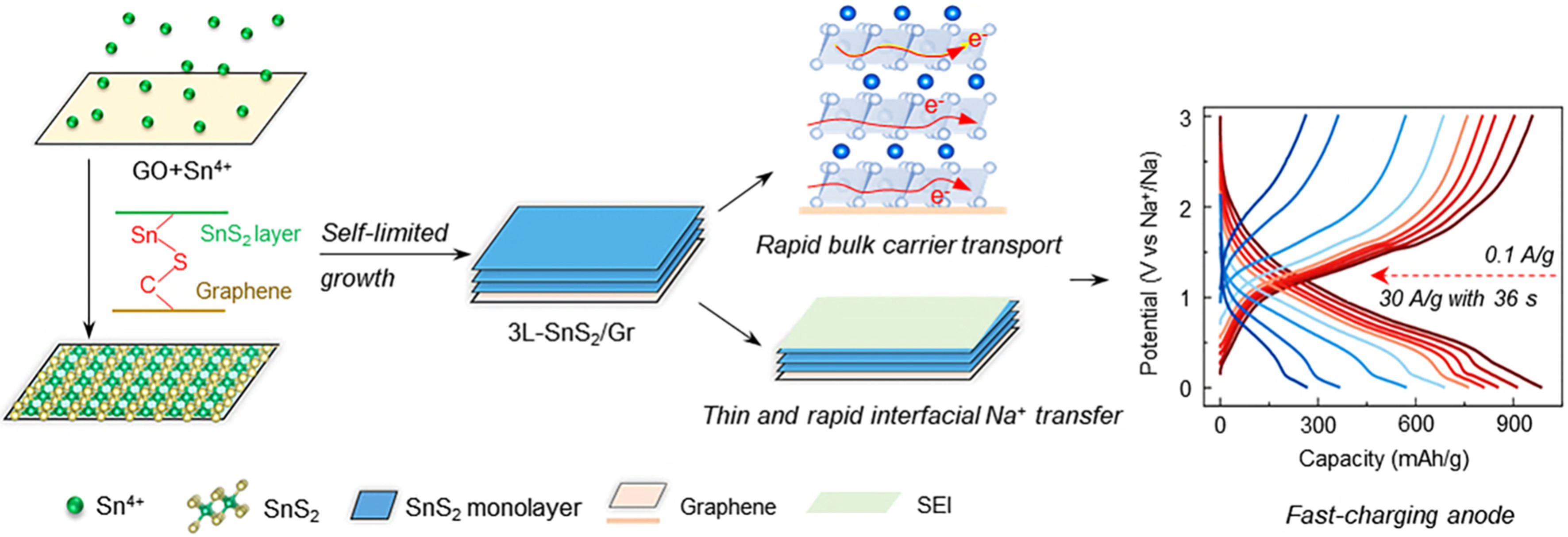
Scheme 1. Schematic illustrations for design strategy of fast-charging sodium-ion batteries. The synthesized atomic-layer level SnS2 anodes generated ultra-thin and NaF, Na2CO3-rich SEI in ester electrolyte (6 nm, Cryo-TEM), achieving fast Na+ transfer at the interface, simultaneously collaborating with efficient carrier transport in the bulk phase enables it can be used as fast-charging anode of sodium-ion batteries Scheme 1. Schematic illustrations for design strategy of fast-charging SIBs. The synthesized atomic-layer level SnS2 anodes generated ultra-thin and NaF, Na2CO3-rich SEI in ester electrolyte (6 nm, Cryo-TEM), achieving fast Na+ transfer at the interface, simultaneously collaborating with efficient carrier transport in the bulk phase enables it can be used as fast-charging anode of SIBs. SEI: Solid-electrolyte interphase; TEM: transmission electron microscopy; SIBs: sodium-ion batteries.
EXPERIMENTAL
Materials preparation
The GO used in this paper was prepared using a modified Hummers method. First, 40 mg of GO, which was preserved in deionized (DI) water, was diluted to 50 mL and further ultrasonicated for 1 h. Then, 0.316 g of SnCl4·5H2O (0.9 mmol) and 0.3 g (4 mmol) of thioacetamide was dissolved in the above dispersion and stirred for 2 h at 35 °C. Subsequently, the obtained stable mixture was hydrothermally treated at 200 °C for 24 h. The products were washed with DI water several times through a vacuum filter. Finally, freeze-drying for 24 h is carried out to obtain 3L-SnS2/Gr.
Materials 1L-SnS2/Gr, 2L-SnS2/Gr and p-SnS2/Gr were synthesized from similar procedures with different dosages of SnCl4·5H2O (0.3, 0.6 and 1.1 mmol) and thioacetamide (TAA, 1.6, 2.4 and 3.0 mmol).
SnS2(Gr) was prepared from a similar procedure with graphene obtained from high-temperature reduction thermal (1,050 °C) of GO for 30 min in Ar atmosphere. Pure SnS2 was prepared using a similar process without adding GO.
Materials characterizations
Synchrotron high-pressure powder X-ray diffraction was carried out at the BL14B1 beamline of the Shanghai Synchrotron Radiation Facility (SSRF) using X-rays with a wavelength of 0.6887 Å. Ex situ X-ray diffraction measurements were performed using X-ray powder diffraction (XRD, BRUKER D8 ADVANCE A25) with Cu Kα radiation (λ = 1.54056 Å) at a scan rate of 1 °/min. The in situ XRD experiments were carried out using the 13-BM-C beamline at advanced photon source (APS) of argonne national laboratory (ANL), with an X-ray wavelength of 0.4332 Å. Synchrotron X-ray absorption near edge structure (XANES) and Fourier-transformed extended X-ray absorption fine structure (FT-EXAFS) tests were conducted in HXMA Beamline at the Canadian Light Source. The microstructures and morphologies of the composites were observed using scanning electron microscopy (SEM, ZEISS Merlin Compact). HAADF-STEM (high angle angular dark field-scanning transmission electron microscopy) images and elemental maps were obtained on a Cs-corrected FEI Titan G2 60-300 Microscope operated at 300 kV. A probe Cs corrector was applied to get better spatial resolution. Ex situ Raman and in-situ Raman spectra were recorded with a 532 nm wavelength on a LabRAM HR spectrometer at room temperature. Chemical bonds and elemental compositions were confirmed via X-ray photoelectron spectroscopy (XPS, ThermoScientific K-Alpha). Specific surface area and pore size distribution were measured on an automated surface area analyzer (ASAP2420-4MP). The ratios of the active materials were determined using a simultaneous thermal analyzer (STA 449 F3). The Zeta potentials of GO, SnCl4 and mixture suspensions were measured using a Nanoplus-3 (Micromeritics). Contact angle is confirmed by Dataphysics OCA20. Cyro-transmission electron microscopy (TEM) was performed using FEI Glacios (USA) operated at 200 kV, which is equipped with an automatic injection system of the frozen sample. All sample preparation processes were operated under Ar atmosphere, and TEM grids are taken out from centrifuge tubes and transferred to the TEM column in the liquid N2. In situ differential electrochemical mass spectrometry (DEMS) experiment was conducted in a custom-made cell obtained from Beijing Scistar Technology Co. Ltd., which was assembled in an argon-filled glove box. Pre-dehydrated helium (99.999%) was employed as the carrier gas. A high flow rate was used to purge the pipeline to remove the air. Then, the flow rate was controlled at 1 mL·min-1 by a gas controller. The gas products during the discharge were carried to pass through an intelligent low-temperature thermostatic bath to condense the electrolyte vapor before entering the mass spectrometer (HPR-20 DEMS, Hiden Analytical).
Electrochemical measurements
To prepare the electrode, the obtained material, Acetylene black and carboxymethyl cellulose (CMC) in a mass ratio of 8:1:1 were mixed together with DI water acting as a dispersion medium. After being ground into a homogeneous slurry, the mixture was uniformly distributed on commercial Cu foil to prepare electrodes. The DI water was thoroughly evaporated at 60 °C under vacuum. After that, electrode disks of
In half cells for SIBs, CR2025 coin-type cells were assembled with sodium foil as the counter electrode. Sodium with diameters of about 16 mm was prepared from sodium bulk in a glove box under the protection of high-purity Ar atmosphere. Glass fiber (Whatman) acted as a separator. The electrolyte for SIBs used was 1 M NaClO4 dissolved in a mixture of ethylene carbonate (EC) and propylene carbonate (PC). Fluoroethylene carbonate (FEC) was added into the electrolyte at the weight percent of about 5% to act as an additive which was beneficial in forming a stable SEI film.
For coin and pouch full cells, the reported Na3V2(PO4)3F2 serves as a cathode. The weight ratio of a cathode to anode is controlled at 8. The voltage window of full cells is set between 1.0 and 3.8 V. The full cell and pouch cell are directly characterized without prefabricated SEI via disassembling the battery. All specific capacities are calculated with the total weight of cathode and anode materials. The data of in situ electrochemical impedance spectroscopy (EIS) were obtained from the Zahner Zennium Pro electrochemical workstation in the frequency range from 100 kHz to 10 mHz. Galvanostatic intermittent titration technique (GITT) tests were performed by discharged/charged at 0.5 A·g-1 with a current pulse duration of 0.5 h and an interval time of 2 h.
RESULTS AND DISCUSSION
The SnS2 with atomic-layer level thickness grown on the graphene is synthesized through heterogeneous nucleation and chemical bond regulation in the hydrothermal process. Firstly, monolayer GO [Supplementary Figure 1] with abundant O-containing groups and SnCl4 raw material were dissolved in the DI water, respectively, which exhibited a zeta potential of -29.13 and 12.00 mV [Supplementary Figure 2]. Then, mixing operation is conducted with a positive zeta potential at 13.53 mV due to electrostatic adsorption force. During the above process, Sn4+ is absorbed on the GO to form SnO2/Gr [Supplementary Figure 3], and Sn(OH)4 grows through heterogeneous nucleation mechanism. Abundant nucleation sites on GO can promote 2D growth of Sn-based compounds. Secondly, TAA plays a role for sulfurization of O element during hydrothermal process, and GO is reduced and assembled for porous structure at different reaction times of 0 min, 30 min, 1 h, 2 h, 4 h, 8 h, 12 h, 16 h, 20 h, 24 h [Supplementary Figures 4 and 5]. By precisely regulating the ratio of Sn raw material, the composites with 1, 2, 3 SnS2 monolayer and SnS2 particle on the graphene (denoted as 1L-SnS2/Gr, 2L-SnS2/Gr, 3L-SnS2/Gr and p-SnS2/Gr) were fabricated [Supplementary Figure 6], respectively.
Synchrotron high-pressure powder X-ray diffraction reveals that the characteristic peaks of 1L-SnS2/Gr, 2L-SnS2/Gr, and 3L-SnS2/Gr are assigned to hexagonal SnS2 (JCPDS: 1-1010) [Figure 1A]. The [001] peaks shift to low angles due to weak Van der Waals force of few-layer SnS2, and their peak intensities gradually grow, indicating a gradual increase in the number of SnS2 layers. 1L-SnS2/Gr, 2L-SnS2/Gr and 3L-SnS2/Gr possess well-defined and 3D interconnected porous networks [Figure 1B and Supplementary Figure 7]. The thin, flake-like nature of the SnS2-based graphene sheets is also evident by the low contrast in the TEM image [Figure 1C and Supplementary Figure 8], which comprises thin layers of SnS2-graphene-SnS2 with sandwich structure [Figure 1C]. Clearly, average thicknesses of 1L-SnS2/Gr, 2L-SnS2/Gr and 3L-SnS2/Gr are estimated to be ≈ 1.6, 2.8 and 4.0 nm, respectively [Figure 1D-F]. Considering thickness (> 0.334 nm) of monolayer graphene with few defects and sandwich structure of composites, the thickness of one side of SnS2 is about 0.633, 1.233 and 1.833 nm, which is nearly 1, 2 and 3-layer SnS2 crystals. Then, a continually increasing amount of Sn raw material, separated SnS2 nanoparticles, appears on the graphene [Supplementary Figure 9]. This may result from the limited chemical bonding force between graphene and SnS2 which only could resist 3-layer SnS2. According to thermogravimetric analysis (TGA) curves, ratios of SnS2 in the 1L-SnS2/Gr, 2L-SnS2/Gr, 3L-SnS2/Gr and p-SnS2/Gr are about 54%, 63%, 75%, and 84%, respectively, and increasing SnS2 ratios are consistent with their Raman spectra [Supplementary Figure 10]. As a comparison, pure graphene is used to fabricate SnS2-based graphene composite SnS2(Gr) without chemical bond force between SnS2 and graphene [Supplementary Figure 11].
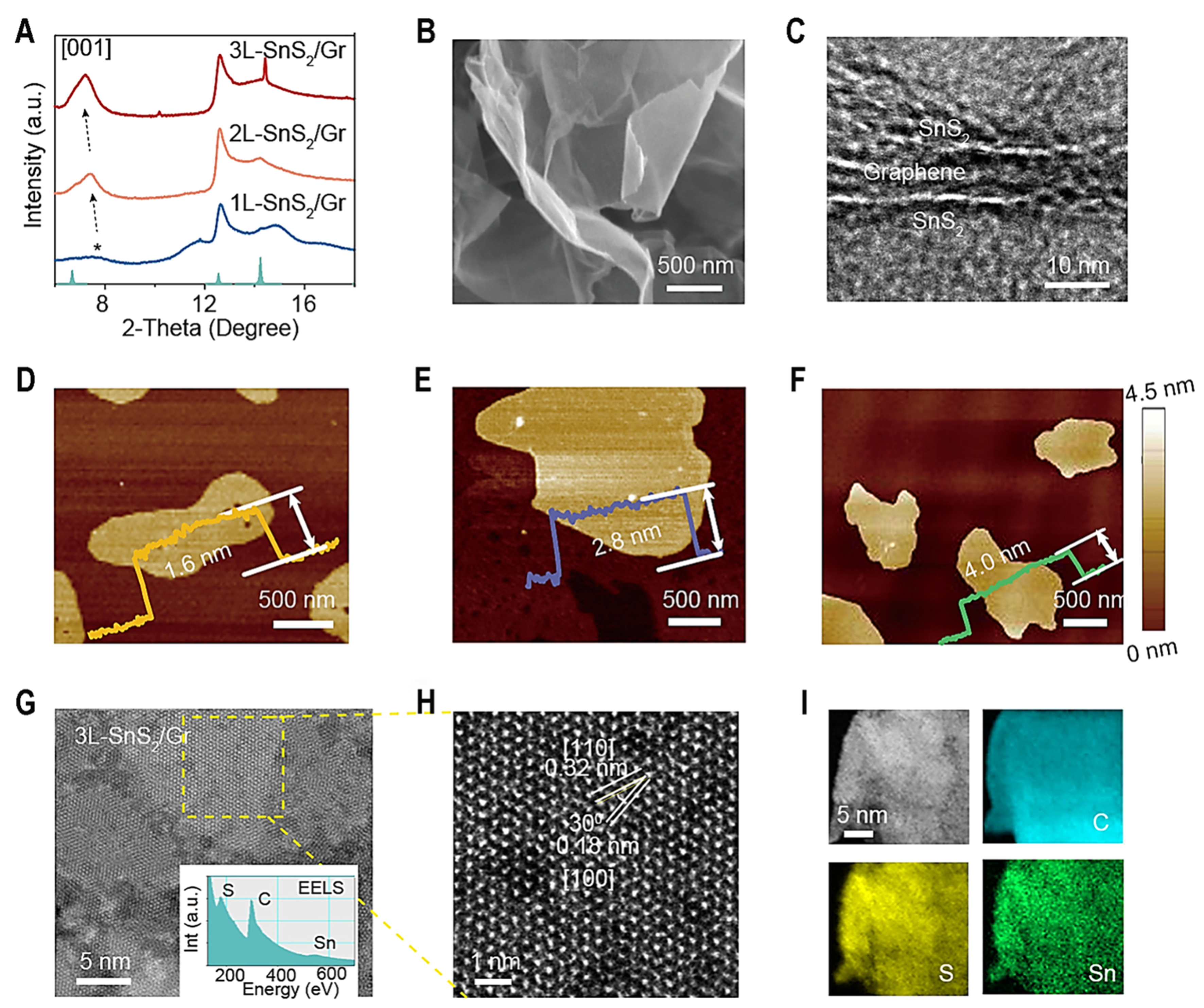
Figure 1. The structural characterization of 1L-SnS2/Gr, 2L-SnS2/Gr, 3L-SnS2/Gr. (A) Synchrotron high-pressure powder XRD pattern of 1L-SnS2/Gr, 2L-SnS2/Gr and 3L-SnS2/Gr; (B) SEM images of 1L-SnS2/Gr; (C) TEM image of 1L-SnS2/Gr; (D) AFM images and height profiles of 1L-SnS2/Gr; (E) 2L-SnS2/Gr; (F) 3L-SnS2/Gr; (G and H) AC-HRTEM images of 3L-SnS2/Gr at different magnifications. Inset in G is EELS image; (I) Elemental mapping image of 3L-SnS2/Gr. XRD: X-ray powder diffraction; SEM: scanning electron microscopy; TEM: transmission electron microscopy; AFM: atomic force microscopy; AC-HRTEM: aberration-corrected high-resolution transmission electron microscopy; EELS: electron energy loss spectroscopy.
The morphology of 3L-SnS2/Gr is further investigated by low-dose TEM[45,46]. As-prepared 3L-SnS2/Gr material displays a homogeneous sheet structure [Figure 1G and H]. The [100] and [110] planes of SnS2 are observed clearly, which can be indexed as hexagonal SnS2. Disappearing of [001] peak for SnS2 and 30° angle of two characteristic peaks of [100] and [110] in these regions demonstrate that growth of SnS2 on the graphene is along the direction of [001] zone axis. According to a fast fourier transformation (FFT) image [Supplementary Figure 12], [100] and [110] lattice distance for typical SnS2 phase and weak graphene signal is also obtained, corresponding to HAADF-STEM results and simulated hexagonal SnS2 selected area electron diffraction (SAED) pattern. The electron energy loss spectroscopy (EELS) spectra display that only C, S and Sn elements can be observed in the 3L-SnS2/Gr. Moreover, homogeneous elemental distribution of these elements reveals the intimate contact between SnS2 and graphene [Figure 1I]. In addition, the surface energy (Supplementary computation method of solid surface free energy) -calculated by Owens-Wendt-Rabel-Kaelble (OWRK) method from contact angles [Supplementary Figure 13] - reveals that the surface energy of 3L-SnS2/Gr (34.89 mJ·m-2) is lower than that of pure SnS2 (53.45 mJ·m-2), suggesting that SnS2 is more inclined to grow on the graphene surface than to form separate particles.
The chemical state of obtained composite is carried out by XPS, X-ray absorption fine structure (XAFS) spectra, and a Fourier transform infrared (FT-IR) spectrometer. High-resolution XPS spectra can be fitted with two splitting peaks of S2- and C–S bond at 162.2 and 164 eV. It is expected that there is no C–S bond in SnS2(Gr) due to pure graphene as raw material without defect, and 23.8%, 16.7% and 12.0% C–S bond can be calculated in the 1L-SnS2/Gr, 2L-SnS2/Gr and 3L-SnS2/Gr [Figure 2A]. C–S chemical bond is formed between SnS2 layers and graphene. According to FT-IR spectra, a C–S chemical bond is also observed in the obtained compounds at 1060 cm-1 [Figure 2B], and no C-S is observed in the SnS2/Gr, which is consistent with the XPS result. In addition, EXAFS spectra show clear Sn-Sn at 3.3 Å and Sn-S at 2.5 Å from the SnS2 crystal
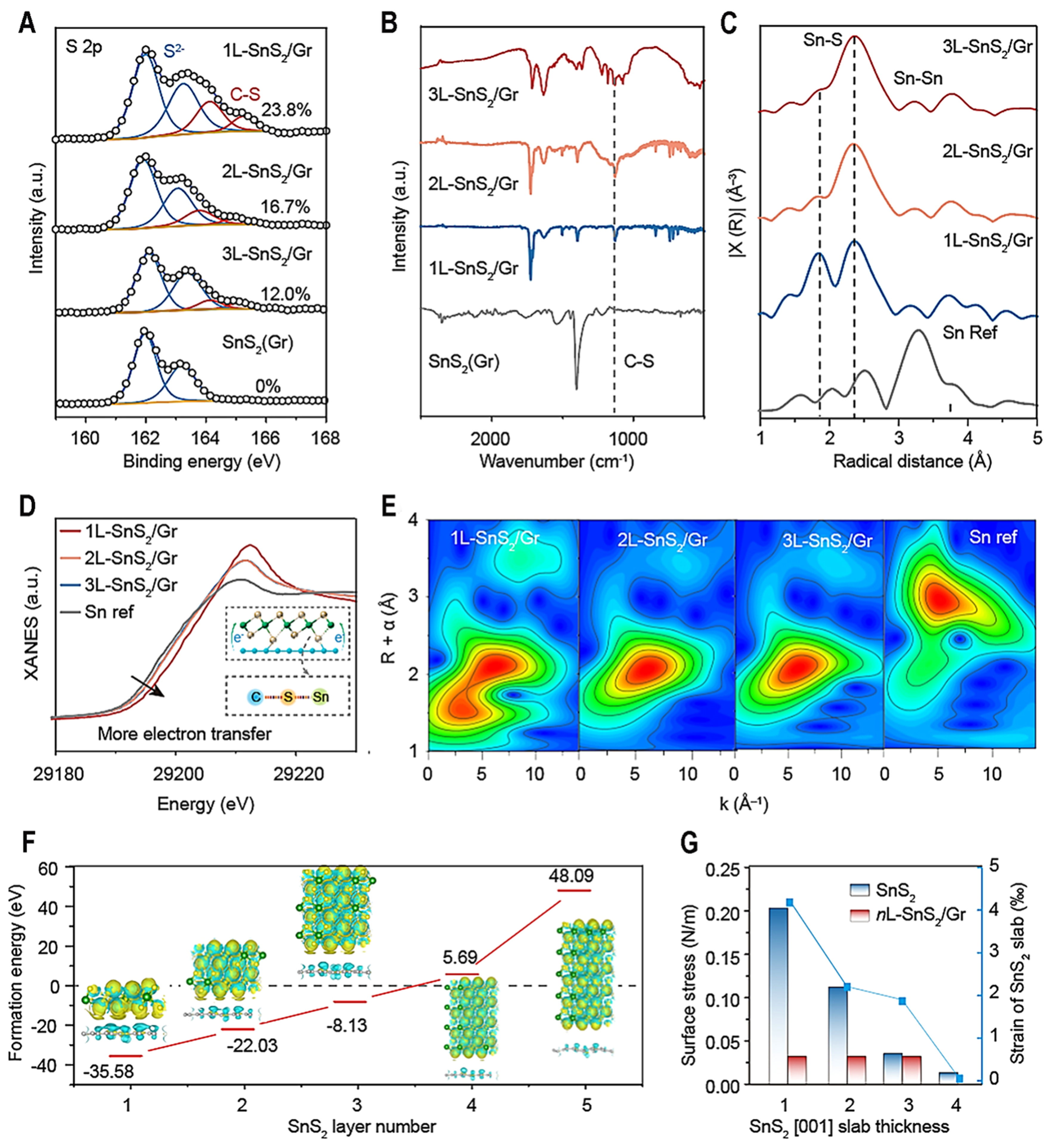
Figure 2. The characterization of chemical bond between SnS2 and graphene. (A) The S 2p high-resolution XPS and (B) FT-IR spectra of 1L-SnS2/Gr, 2L-SnS2/Gr, 3L-SnS2/Gr and SnS2 (Gr); (C) The EXAFS; (D) XANES curves; (E) Wavelet transform images of 1L-SnS2/Gr, 2L-SnS2/Gr, 3L-SnS2/Gr and Sn metal; (F) Calculated formation energies of 1L-SnS2/Gr, 2L-SnS2/Gr, 3L-SnS2/Gr, 4L-SnS2/Gr, 5L-SnS2/Gr. Inset: Differential charge densities of relative models. Yellow and cyan isosurfaces show electron gain and loss (0.003 Bohr-3), respectively; (G) Surface stress and strain of SnS2 and nL-SnS2/Gr with different layers. XPS: X-ray photoelectron spectroscopy; FT-IR: fourier transform infrared; EXAFS: extended X-ray absorption fine structure; XANES: X-ray absorption near edge structure.
Density functional theory (DFT) calculation (Supplementary DFT computation Methods) is used to characterize the stability of obtained atomic-layer level SnS2 composites. The formation energies[26,48] of 1L-SnS2/Gr, 2L-SnS2/Gr, 3L-SnS2/Gr, 4L-SnS2/Gr, and 5L-SnS2/Gr are -35.58, -22.03, -8.13, 5.69, and
Selected 3L-SnS2/Gr with relatively high-loading active SnS2 as the main research object is further explored with various characterization techniques. The 3L-SnS2/Gr delivers reversible capacities of 983, 910, 851, 807, 760, 686, 569, 364 and 264 mAh·g-1 at the current densities of 0.1, 0.2, 0.5, 1.0, 2.0, 5.0, 10.0, 20.0 and
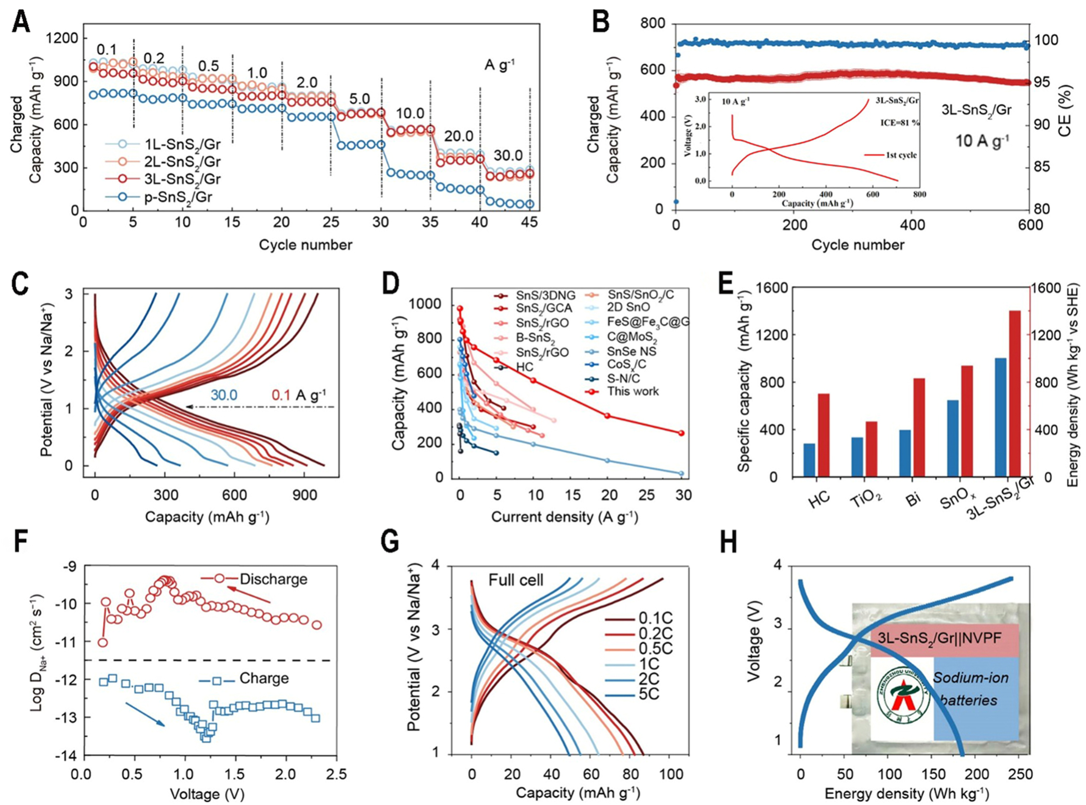
Figure 3. Electrochemical performance of 3L-SnS2/Gr and p-SnS2/Gr in SIBs. (A) Rate performances of 3L-SnS2/Gr and p-SnS2/Gr at various current densities; (B) Cycling stability of 3L-SnS2/Gr at 10 A·g-1. Inset: initial discharge-charge curve; (C) Charge/discharge curves of 3L-SnS2/Gr at different current densities; (D) Rate performance comparison between this work and other reported literature; (E) Comparison of different anode materials according to specific capacity and energy density with SHE cathode; (F) GITT curves of 3L-SnS2/Gr at second cycle; (G) Charge/discharge curves of full cell at different rates with 3L-SnS2/Gr anodes with Na3V2(PO4)3 F2 cathodes; (H) Voltage-energy density curves and optical image of assembled pouch full cell. SIBs: Sodium-ion batterys; SHE: standard hydrogen electrode; GITT: galvanostatic intermittent titration technique.
From EIS curves, 3L-SnS2/Gr exhibits lower interfacial and charge transfer impedance during the discharging process, suggesting its low polarization [Supplementary Figure 20A]. In addition, 3L-SnS2/Gr demonstrates high capacities of 620 and 570 mAh·g-1 at 1 A·g-1 at 2 and 3 mg·cm-2, respectively, after 100 cycles [Supplementary Figure 20B]. It can be calculated that Na+ diffusion coefficient was about 1 × 10⁻¹⁰ cm2·s-1 during whole charge/discharge process [Figure 3F]. In addition, the surface capacitive contribution is calculated and reaches the value of 85% at 2 mV·s-1. The b-values of 0.870 and 0.863 for cathodic and anodic peaks can be quantified [Supplementary Figure 19], suggesting a dominating surface capacitive behavior. A high Na+ diffusion coefficient and the contribution of surface capacitive effect indicate a rapid redox reaction and an abundant electron/ion transfer channel owing to an atomically thin 2D film of SnS2 bonded with graphene structure. The electrochemical performance of 3L-SnS2/Gr in full-cell was tested with
The electronic structure and ion transfer properties of 1L-SnS2/Gr, 2L-SnS2/Gr, 3L-SnS2/Gr and bulk SnS2 are calculated using DFT. The interaction force between graphene and SnS2 can lead to a downward shift in the density of states and make rich electrons at the Fermi level, suggesting that the electronic conductivity of SnS2 is enhanced [Figure 4A-C]. For 3L-SnS2/Gr, the corresponding Na+ diffusion energy barriers are 0.205, 0.204 and 0.21 eV via different paths, respectively, which can explain their similar electrochemical performance [Figure 4D]. Compared with the low Na+ diffusion energy barrier (0.498 eV) of bulk SnS2, the obtained 1L-SnS2/Gr, 2L-SnS2/Gr and 3L-SnS2/Gr materials exhibited much lower energy barriers [Figure 4E], indicating enhanced Na+ transfer speeds. The high electrical conductivity and ion transport realize its high reduction capability for decomposition of FEC[24], which is consistent with the experimental result. To rationalize obtained superior electrochemical performance in SIBs, in situ differential electrochemistry mass spectrometry (DEMS)[49,50] and Cyro-TEM are used to characterize the formation process and structure of SEI for 3L-SnS2/Gr and p-SnS2/Gr. The used electrolyte is made of NaClO4 salt, EC and PC solvent and FEC additive. It is observed that C2H4 and CO were released when discharging to 0.6 V [Figure 4F and G], and it almost stops during charging process. C2H4 and CO gas mainly results from the reduction of EC and PC molecules. The gas amount of 3L-SnS2/Gr is lower than that of p-SnS2/Gr, suggesting less electrolyte decomposition to form SEI. Correspondingly, SEI of 3L-SnS2/Gr (~ 6 nm) is thinner than that of p-SnS2/Gr (12 nm), which contains much NaF species and Na2CO3 species [Figure 4H]. During 3L-SnS2/Gr discharging, the FEC additive performs double electron reduction decomposition to generate a large amount of NaF and Na2CO3, and quickly forms a thin and stable SEI film[51]. Low content of Na2O and organic components in SEI indicates the little consumption of solvent molecules. These processes can be expressed as
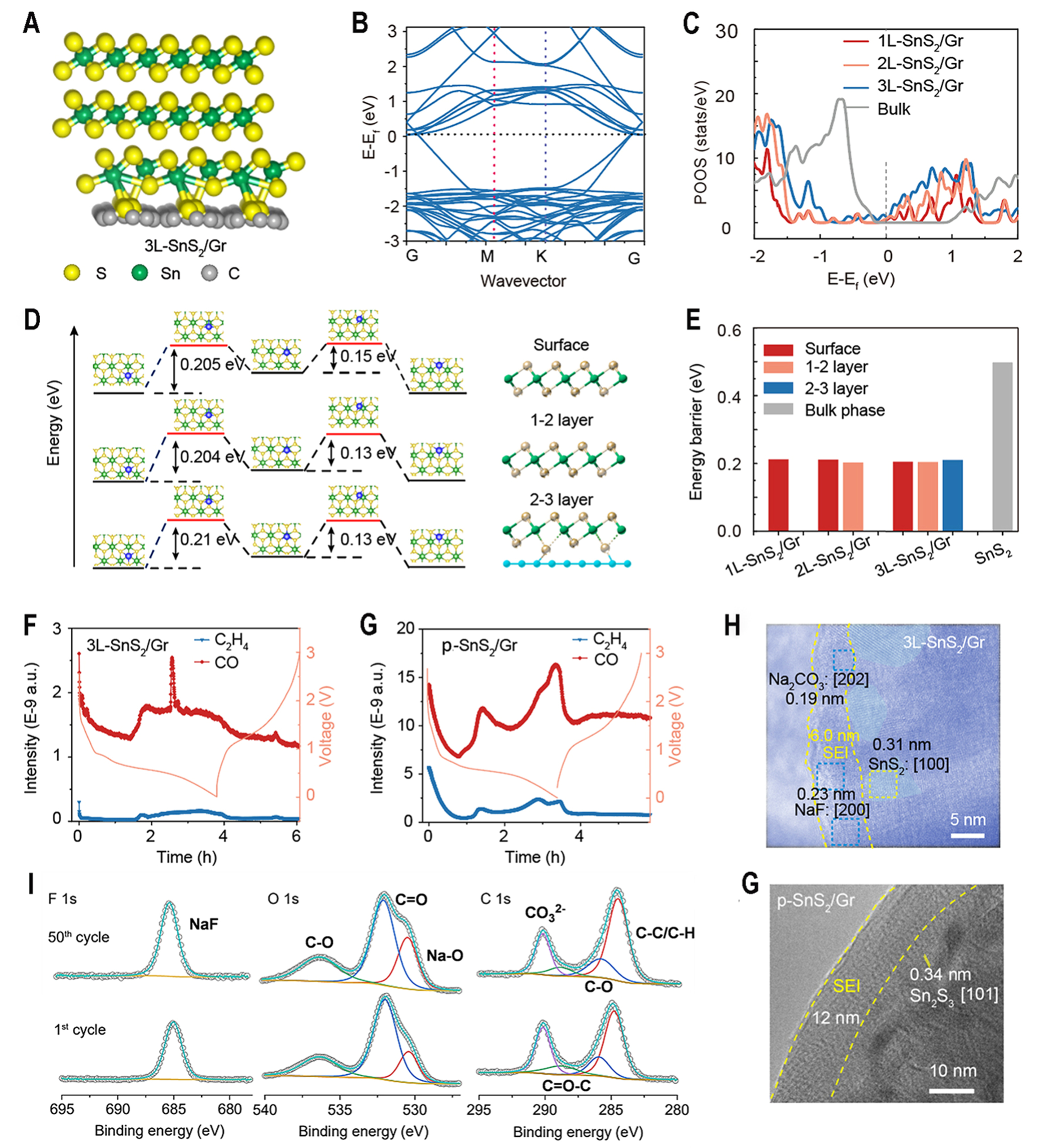
Figure 4. SEI characterization and relative theoretical calculation. (A) Structural model and (B) band structure for 3L-SnS2/Gr; (C) Density of states of as-obtained 1L-SnS2/Gr, 2L-SnS2/Gr, 3L-SnS2/Gr and bulk SnS2. The Fermi level is set at zero; (D) Transition paths of sodium atom diffusion for 3L-SnS2/Gr through surface, 1-2 layer and 2-3 layer path, as shown in right model; (E) Energy barrier of 1L-SnS2/Gr, 2L-SnS2/Gr,3L-SnS2/Gr and bulk SnS2 through different Na+ diffusion paths; (F and G) In situ DEMS of 3L-SnS2/Gr and p-SnS2/Gr; (H) Cyro-TEM image of 3L-SnS2/Gr after one cycle; (I) F 1 s, O 1 s and C 1 s XPS spectra of SEI on the 3L-SnS2/Gr after one cycle and 50 cycles; (J) Cyro-TEM image of p-SnS2/Gr after one cycle. SEI: Solid-electrolyte interphase; DEMS: differential electrochemical mass spectrometry; TEM: transmission electron microscopy; XPS: X-ray photoelectron spectroscopy.
“FEC + 2e- + 2Na+ → CH3 (CH = CH)n CH3 + Na2CO3 + NaF
2H2O + 2e- → 2NaOH + H2 ↑ 2NaOH + 2e- + 2Na+ → Na2O + H2 ↑
EC + 2e- + 2Na+ → Na2CO3 + CH = CH2 ↑ EC + 2e- + 2Na+ → (CHONa)2 + CO
PC + 2e- + 2Na+ → NaOCH(CH3) CH2ONa + CO ↑”
According to XPS of 3L-SnS2/Gr, the C 1 s spectrum at 290.54 eV (CO32-), and the F 1 s spectra at 685.80 eV (Na-F) peaks indicate the presence of inorganic components Na2CO3 and NaF, respectively [Figure 4I]. The Na2O is derived from the decomposition of solvent molecules, while NaF and Na2CO3 are produced by the decomposition of FEC. The almost unchanged element content also demonstrates that SEI components of 3L-SnS2/Gr are stable [Supplementary Figure 21]. However, thick SEI (12 nm) of p-SnS2/Gr mainly consists of organic species [Figure 4J]. The above result indicates that FEC additives would decompose extensively in the cycling process of 3L-SnS2/Gr, suppressing the subsequent decomposition of EC and PC solvents for providing a stable cycling environment for the batteries.
Except for the electrode-electrolyte interphase, bulk particle contact also has an important influence on the reaction kinetics of SIBs. According to in situ high-energy XRD of discharging process [Figure 5A], the initial SnS2 phase is transformed to Sn2S3 at 1.2 V and metallic Sn at 0.8 V with Na2S phase. Then, obvious characteristic peaks corresponding to Na15Sn4 alloy[25] can be observed after discharging to 0.5 and 0.01 V due to alloying reaction. A weak characterized peak of SnS2 can be observed from ex situ XRD patterns at 3.0 V, suggesting its amorphous or ultrafine nanostructure [Supplementary Figure 22A]. Moreover, the conversion reaction of SnS2[52] was also confirmed by in situ Raman, with the vibration of the Sn–S bond gradually shifting to low wavenumbers and eventually disappearing [Supplementary Figure 22B]. Ex situ Raman spectra also show that the characteristic peak of SnS2 can be recovered after charging to 3.0 V, providing strong evidence about reversible electrochemical reaction of as-synthesized 3L-SnS2/Gr electrodes [Supplementary Figure 22C]. According to a Cyro-TEM image at charging to 3.0 V [Figure 4H], [100] region of SnS2 is observed, suggesting its high conversion reaction reversibility.
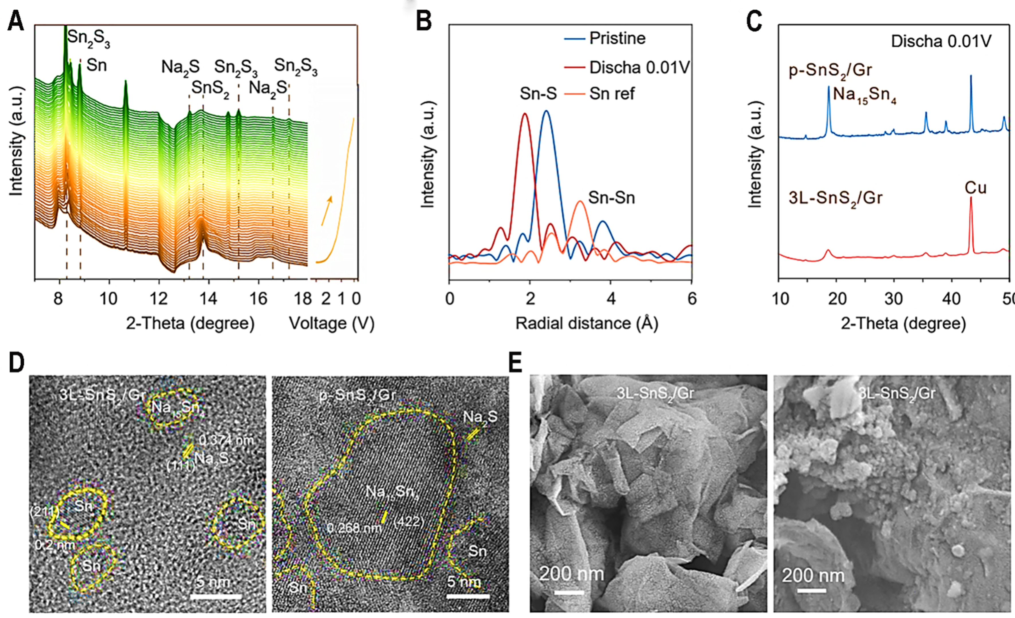
Figure 5. Electrochemical reaction mechanism of as-synthesized 3L-SnS2/Gr. (A) In situ high energy XRD with wavelength of 0.4332 Å during discharging process; (B) EXAFS data of 3L-SnS2/Gr for pristine state, discharged to 0.01 V and Sn ref.; (C) XRD patterns of p-SnS2/Gr and 3L-SnS2/Gr at discharging to 0.01 V; (D) Cryo-TEM images of 3L-SnS2/Gr and p-SnS2/Gr at discharging to 0.8 V; (E) SEM images of 3L-SnS2/Gr and p-SnS2/Gr after 100 cycles. XRD: X-ray powder diffraction; EXAFS: extended X-ray absorption fine structure; TEM: transmission electron microscopy; SEM: scanning electron microscopy.
Conversion reaction:
SnS2 → 1/2Sn2S3 + 1/2Na2S,
1/2Sn2S + 3Na+ + 3e → Sn + 3/2Na2S
Alloy reaction:
Sn + 3.75Na+ + 3.75e- → Na3.75Sn
EXAFS and TEM were used to analyze the chemical bond and structural changes during the cycling process. It can be observed that Sn–S and Sn–Sn bonds can be detected [Figure 5B] for 3L-SnS2/Gr at discharging to 0.01 V. Interestingly, Sn–S chemical bond at 1.9 Å becomes stronger at discharging to 0.01 V, suggesting that volume expansion leads to more abundant contact, enhancing the ratio of C–S bonds to influence surrounding chemical environment of the Sn element. This can benefit enough solid phase contact for high reaction reversibility and cycling stability. Particle size from XRD data [Figure 5C] at discharged state suggested that 3L-SnS2/Gr possesses smaller diameter; this benefits from atomically thin thickness of SnS2 with the help of C–S bonding. Figure 5D clearly shows the grain size of discharged products for 3L-SnS2/Gr and p-SnS2/Gr. Sn(211), Na2S(111) and Na15Sn4 (422) of 3L-SnS2/Gr and p-SnS2/Gr are obviously observed [Figure 5D]. After discharging to 0.01 V, discharged product of 3L-SnS2/Gr possesses a weaker XRD peak of Na15Sn4, suggesting its smaller particle and lower crystallinity. According to TEM result, two electrodes all present lattice fringes of Sn-Na alloy and Na2S due to the conversion and alloy reaction of SnS2. The smallest crystal regions around 1-2 nm with short lattice fringes appear in the 3L-SnS2/Gr [Figure 5D]. In contrast, p-SnS2/Gr electrodes show larger crystals with the size of 8-12 nm. The above result indicates that atomically thin SnS2 can effectively inhibit crystal agglomeration and fabricate high reaction contact during discharge process. SEM images [Figure 5E] also support this point that p-SnS2/Gr displays obvious particles, while phase product of 3L-SnS2/Gr is too small to survey.
CONCLUSION
In summary, this work rationally designed a self-limiting atomic-layer SnS2/graphene anode material for fast-charging sodium-ion batteries. A self-limiting growth strategy enabled the controllable fabrication of tunable, atomically thin 1-3 layers of SnS2 on graphene. Theoretical and multiscale experimental analyses reveal that the improved performance stems from enhanced bulk ion/electron transport, coupled with an induced ultrathin, inorganic-rich SEI, which together boost reaction kinetics and cycling stability. The designed anode delivers a fast-charging capacity of 300 mAh·g-1 within 36 s at 30 A·g-1, along with outstanding long-term cycling durability. This work provides valuable insights into precise atomic-scale material synthesis and contributes to the development of high-performance fast-charging batteries.
DECLARATIONS
Authors’ contributions
Responsible for high-end characterization and testing: Yang, T.; Liu, Q.; Dai, H.; Sun, S.; Liu, L.; Han, Y.
Made substantial contributions to conception, article revision and design of the study: Chen, W.
Responsible for data analysis and interpretation: Cao, Y.
Experimental operation, graphics drawing and data processing: Gai, J.; Song, K.; Du, H.
Theoretical calculation: Pang, R.; Li, S.
Provided administrative, technical, and material support: Cao, Y.; Han, Y.; Chen, W.
Availability of data and materials
The raw data supporting the findings of this study are available within this Article and its Supplementary Materials. Further data are available from the corresponding authors upon request.
Financial support and sponsorship
National Natural Science Foundation of China (Nos. U24A200471, 22279121, 22109165), Science Technology and Innovation Team in University of Henan Province (24IRTSTHN002), Joint Fund of Scientific and Technological Research and Development Program of Henan Province (222301420009) and the founding of Zhengzhou University.
Conflicts of interest
All authors declared that there are no conflicts of interest.
Ethical approval and consent to participate
Not applicable.
Consent for publication
Not applicable.
Copyright
© The Author(s) 2026.
Supplementary Materials
REFERENCES
1. Wang, C. Y.; Liu, T.; Yang, X. G.; et al. Fast charging of energy-dense lithium-ion batteries. Nature 2022, 611, 485-90.
2. Ye, L.; Lu, Y.; Wang, Y.; Li, J.; Li, X. Fast cycling of lithium metal in solid-state batteries by constriction-susceptible anode materials. Nat. Mater. 2024, 23, 244-51.
3. Kim, Y. H.; An, J. H.; Kim, S. Y.; et al. Enabling 100C fast-charging bulk Bi anodes for Na-Ion batteries. Adv. Mater. 2022, 34, e2201446.
4. Li, Y.; Vasileiadis, A.; Zhou, Q.; et al. Origin of fast charging in hard carbon anodes. Nat. Energy. 2024, 9, 134-42.
5. Luo, F.; Roy, A.; Silvioli, L.; et al. P-block single-metal-site tin/nitrogen-doped carbon fuel cell cathode catalyst for oxygen reduction reaction. Nat. Mater. 2020, 19, 1215-23.
6. Ge, J.; Fan, L.; Rao, A. M.; Zhou, J.; Lu, B. Surface-substituted Prussian blue analogue cathode for sustainable potassium-ion batteries. Nat. Sustain. 2022, 5, 225-34.
7. Lv, Z.; Zhao, C.; Xie, M.; et al. 1D insertion chains induced small-polaron collapse in MoS2 2D layers toward fast-charging sodium-ion batteries. Adv. Mater. 2024, 36, e2309637.
8. Sun, H.; Mei, L.; Liang, J.; et al. Three-dimensional holey-graphene/niobia composite architectures for ultrahigh-rate energy storage. Science 2017, 356, 599-604.
9. Choi, J. H.; Kim, D. W.; Jung, D. H.; Kim, K.; Kim, J.; Kang, J. K. Low-crystallinity conductive multivalence iron sulfide-embedded S-doped anode and high-surface area O-doped cathode of 3D porous N-rich graphitic carbon frameworks for high-performance sodium-ion hybrid energy storages. Energy. Storage. Materials. 2024, 68, 103368.
10. Vaalma, C.; Buchholz, D.; Weil, M.; Passerini, S. A cost and resource analysis of sodium-ion batteries. Nat. Rev. Mater. 2018, 3, 18013.
11. Fang, Y.; Luan, D.; Lou, X. W. D. Recent advances on mixed metal sulfides for advanced sodium-ion batteries. Adv. Mater. 2020, 32, e2002976.
12. Wan, Y.; Huang, B.; Liu, W.; Chao, D.; Wang, Y.; Li, W. Fast-charging anode materials for sodium-ion batteries. Adv. Mater. 2024, 36, e2404574.
13. Zhou, X.; Chen, X.; Kuang, W.; et al. Entropy-assisted anion-reinforced solvation structure for fast-charging sodium-ion full batteries. Angew. Chem. Int. Ed. Engl. 2024, 63, e202410494.
14. Wu, L.; Zheng, J.; Wang, L.; et al. PPy-encapsulated SnS2 nanosheets stabilized by defects on a TiO2 support as a durable anode material for lithium-ion batteries. Angew. Chem. Int. Ed. Engl. 2019, 58, 811-5.
15. Li, X.; Zhang, X.; Niu, X.; et al. Strain retarding in multilayered hierarchical Sn‐doped Sb nanoarray for durable sodium storage. Adv. Funct. Mater. 2023, 33, 2300914.
16. Song, K.; Wang, X.; Xie, Z.; et al. Ultrathin CuF2 ‐rich solid‐electrolyte interphase induced by cation‐tailored double electrical layer toward durable sodium storage. Angewandte. Chemie. 2023, 135, e202216450.
17. Yang, M.; Chang, X.; Wang, L.; et al. Interface modulation of metal sulfide anodes for long-cycle-life sodium-ion batteries. Adv. Mater. 2023, 35, e2208705.
18. Li, Y.; Zhou, Q.; Weng, S.; et al. Interfacial engineering to achieve an energy density of over 200 Wh kg-1 in sodium batteries. Nat. Energy. 2022, 7, 511-9.
19. Pei, F.; Wu, L.; Zhang, Y.; et al. Interfacial self-healing polymer electrolytes for long-cycle solid-state lithium-sulfur batteries. Nat. Commun. 2024, 15, 351.
20. Tu, Z.; Choudhury, S.; Zachman, M. J.; et al. Designing artificial solid-electrolyte interphases for single-ion and high-efficiency transport in batteries. Joule 2017, 1, 394-406.
21. Ou, X.; Cao, L.; Liang, X.; et al. Fabrication of SnS2/Mn2SnS4/carbon heterostructures for sodium-ion batteries with high initial coulombic efficiency and cycling stability. ACS. Nano. 2019, 13, 3666-76.
22. Hu, R.; Ouyang, Y.; Liang, T.; et al. Inhibiting grain coarsening and inducing oxygen vacancies: the roles of Mn in achieving a highly reversible conversion reaction and a long life SnO2-Mn-graphite ternary anode. Energy. Environ. Sci. 2017, 10, 2017-29.
23. Wang, C.; He, Q.; Halim, U.; et al. Monolayer atomic crystal molecular superlattices. Nature 2018, 555, 231-6.
24. Klein, F.; Pinedo, R.; Berkes, B. B.; Janek, J.; Adelhelm, P. Kinetics and degradation processes of CuO as conversion electrode for sodium-ion batteries: an electrochemical study combined with pressure monitoring and DEMS. J. Phys. Chem. C. 2017, 121, 8679-91.
25. Wang, J. W.; Liu, X. H.; Mao, S. X.; Huang, J. Y. Microstructural evolution of tin nanoparticles during in situ sodium insertion and extraction. Nano. Lett. 2012, 12, 5897-902.
26. Han, W.; Huang, P.; Li, L.; et al. Two-dimensional inorganic molecular crystals. Nat. Commun. 2019, 10, 4728.
27. Huang, J.; Guo, X.; Du, X.; et al. Nanostructures of solid electrolyte interphases and their consequences for microsized Sn anodes in sodium ion batteries. Energy. Environ. Sci. 2019, 12, 1550-7.
28. Zhang, Y. Y.; Zhang, C. H.; Guo, Y. J.; et al. Refined electrolyte and interfacial chemistry toward realization of high-energy anode-free rechargeable sodium batteries. J. Am. Chem. Soc. 2023, 145, 25643-52.
29. Liu, J.; Xie, D.; Xu, X.; et al. Reversible formation of coordination bonds in Sn-based metal-organic frameworks for high-performance lithium storage. Nat. Commun. 2021, 12, 3131.
30. Liu, Q.; Jiang, W.; Xu, J.; et al. A fluorinated cation introduces new interphasial chemistries to enable high-voltage lithium metal batteries. Nat. Commun. 2023, 14, 3678.
31. Xu, J.; Zhang, J.; Pollard, T. P.; et al. Electrolyte design for Li-ion batteries under extreme operating conditions. Nature 2023, 614, 694-700.
32. Luo, J.; Yang, M.; Wang, D.; et al. A fast na-ion conduction polymer electrolyte via triangular synergy strategy for quasi-solid-state batteries. Angew. Chem. Int. Ed. Engl. 2023, 62, e202315076.
33. Deng, T.; Cao, L.; He, X.; et al. In situ formation of polymer-inorganic solid-electrolyte interphase for stable polymeric solid-state lithium-metal batteries. Chem 2021, 7, 3052-68.
34. Li, W.; Guo, X.; Song, K.; et al. Binder‐induced ultrathin SEI for defect‐passivated hard carbon enables highly reversible sodium‐ion storage. Adv. Energy. Mater. 2023, 13, 2300648.
35. Song, W.; Scholtis, E. S.; Sherrell, P. C.; et al. Electronic structure influences on the formation of the solid electrolyte interphase. Energy. Environ. Sci. 2020, 13, 4977-89.
36. Chao, D.; Zhu, C.; Yang, P.; et al. Array of nanosheets render ultrafast and high-capacity Na-ion storage by tunable pseudocapacitance. Nat. Commun. 2016, 7, 12122.
37. Cha, E.; Patel, M. D.; Park, J.; et al. 2D MoS2 as an efficient protective layer for lithium metal anodes in high-performance Li-S batteries. Nat. Nanotechnol. 2018, 13, 337-44.
38. Liang, H. J.; Liu, H. H.; Zhao, X. X.; et al. Electrolyte chemistry toward ultrawide-temperature (-25 to 75 °C) sodium-ion batteries achieved by phosphorus/silicon-synergistic interphase manipulation. J. Am. Chem. Soc. 2024, 146, 7295-304.
39. Wang, X.; He, Y.; Liu, S.; et al. Dynamic concentration of alloying element on anode surface enabling cycle‐stable Li metal batteries. Adv. Funct. Mater. 2023, 33, 2307281.
40. Manzeli, S.; Ovchinnikov, D.; Pasquier, D.; Yazyev, O. V.; Kis, A. 2D transition metal dichalcogenides. Nat. Rev. Mater. 2017, 2, 17033.
41. Wang, D.; Zhou, C.; Filatov, A. S.; et al. Direct synthesis and chemical vapor deposition of 2D carbide and nitride MXenes. Science 2023, 379, 1242-7.
42. Gao, Y. J.; Cui, C. H.; Huang, Z. K.; et al. Lithium pre-storage enables high initial coulombic efficiency and stable lithium-enriched silicon/graphite anode. Angew. Chem. Int. Ed. Engl. 2024, 63, e202404637.
43. Xiong, P.; Zhang, F.; Zhang, X.; et al. Strain engineering of two-dimensional multilayered heterostructures for beyond-lithium-based rechargeable batteries. Nat. Commun. 2020, 11, 3297.
44. Zhang, D.; Zhu, Y.; Liu, L.; et al. Atomic-resolution transmission electron microscopy of electron beam-sensitive crystalline materials. Science 2018, 359, 675-9.
45. Wan, Y.; Song, K.; Chen, W.; et al. Ultra-high initial coulombic efficiency induced by interface engineering enables rapid, stable sodium storage. Angew. Chem. Int. Ed. Engl. 2021, 60, 11481-6.
46. Novoselov, K. S.; Mishchenko, A.; Carvalho, A.; Castro, N. A. H. 2D materials and van der Waals heterostructures. Science 2016, 353, aac9439.
47. Lu, Z.; Yang, H.; Guo, Y.; et al. Consummating ion desolvation in hard carbon anodes for reversible sodium storage. Nat. Commun. 2024, 15, 3497.
48. Wang, Q.; Wang, C.; Qiao, Y.; Zhou, H.; Yu, J. Hybrid-electrolytes system established by dual super-lyophobic membrane enabling high-voltage aqueous lithium metal batteries. Adv. Mater. 2024, 36, e2401486.
49. Zhang, J.; Yan, Y.; Wang, X.; et al. Bridging multiscale interfaces for developing ionically conductive high-voltage iron sulfate-containing sodium-based battery positive electrodes. Nat. Commun. 2023, 14, 3701.
50. Guo, X.; Xie, Z.; Wang, R.; et al. Interface-compatible gel-polymer electrolyte enabled by NaF-solubility-regulation toward all-climate solid-state sodium batteries. Angew. Chem. Int. Ed. Engl. 2024, 63, e202402245.
51. Wang, J.; Yang, Y.; Chen, J.; et al. Spatial confinement of Co1.67Te2 nanoparticles within porous carbon nanofibers enabling fast kinetics and stability for sodium dual-ion batteries. Energy. Storage. Materials. 2024, 71, 103578.
52. Chong; P. et al. Three-dimensional structure S-SnS2/NSG with sulfur vacancies for high-performance lithium-ion batteries. J. Alloys. Compd. 2023, 939, 168828.
Cite This Article

How to Cite
Download Citation
Export Citation File:
Type of Import
Tips on Downloading Citation
Citation Manager File Format
Type of Import
Direct Import: When the Direct Import option is selected (the default state), a dialogue box will give you the option to Save or Open the downloaded citation data. Choosing Open will either launch your citation manager or give you a choice of applications with which to use the metadata. The Save option saves the file locally for later use.
Indirect Import: When the Indirect Import option is selected, the metadata is displayed and may be copied and pasted as needed.
About This Article
Copyright

Data & Comments
Data
0


Comments
Comments must be written in English. Spam, offensive content, impersonation, and private information will not be permitted. If any comment is reported and identified as inappropriate content by OAE staff, the comment will be removed without notice. If you have any queries or need any help, please contact us at support@oaepublish.com.