

Catalytic methane decomposition process on carbon-based catalyst under contactless induction heating

Abstract
Hydrogen obtained from decomposition of natural gas with direct sequestration of carbon in solid form could be an attractive and cost-effective alternative for large-scale hydrogen production. We report here the use of a carbon-based catalyst to achieve the catalytic decomposition of methane (CMD) at medium temperature, 800 °C, under induction heating (IH). Analyses of the catalytic results and characterizations of the spent catalyst have shown that the carbon deposited during the reaction acts as the active phase for the reaction and can, therefore, be recycled infinitely. This autocatalytic effect can only be observed when the carbon catalyst operates under IH because the same catalyst operating under Joule heating (JH) deactivates rapidly in the same way as that already reported in the literature and no autocatalytic effect has been observed. The carbon formed is in the form of a graphene layer with a high degree of graphitization and is completely different from the carbon black powder obtained in other processes. These promising results could lay the groundwork for the development of an industrially and economically viable way to convert natural gas into turquoise hydrogen, using renewable energy and low-cost catalysts, with better resistance to poisoning by impurities present in the processing load. The combination of a carbon-based catalyst and non-contact IH could also lead to combined catalytic processes for many challenging reactions.

Keywords
INTRODUCTION
Hydrogen is used in numerous chemical processes and also as an energy carrier to help the decarbonization of different sectors to mitigate the greenhouse gas emissions. It is mostly produced from methane, the main component of natural gas, through different processes such as steam reforming, autothermal reforming, and partial oxidation[1-4]. Hydrogen production from natural gas offers numerous advantages such as low cost, mature technology, flexibility, and well-developed infrastructure. However, most of these technologies involve significant CO2 emissions due to the huge amount of fuel gas required to heat the catalyst. Hydrogen production is estimated to account for 3% of global CO2 emissions, of which 17%-41% is the direct product of hydrocarbon combustion[5-7]. Methane steam reforming, also known as SMR, is an endothermic reaction, and the use of a low thermal catalyst in the reaction leads to a temperature gradient across the catalyst bed. To ensure a uniform temperature within the reactor, combustion must be maintained at extremely high levels to guarantee the transfer of heat flow to the catalyst. The requirement for such high operation temperature is a consequence of the poor thermal efficiency of conventional reactors, typically below 50%[8]. Therefore, hydrogen production with direct carbon capture and storage operated with a higher energy-efficient mode represents an alternative to these existing processes.
Natural gas-based hydrogen production is anticipated to remain the primary method of global hydrogen production in the foreseeable future[9]. The catalytic decomposition of methane (CMD) has been developed over the last decades and has recently attracted increasing interest from academia and industry as a simple way to produce hydrogen in a decentralized manner, i.e., on-site and on-demand, without concomitant CO2 release typical of traditional production processes, including those from transportation[10-16].
In the CMD process, methane from large natural reserves or shale gas is directly decomposed on a catalyst to produce hydrogen and solid carbon, avoiding costly CO2 capture after treatment. Additionally, it should be noted that CMD processes operate under near-atmospheric pressure conditions, which may offer an advantage over other hydrogen production methods such as steam reforming that require higher pressures. CMD technology can be used for on-site CO-free hydrogen production, which can be part of combined heat/power and mobile applications. This approach helps avoid the need for long-distance hydrogen transport, addressing safety and cost investment concerns due to scarce hydrogen transport infrastructure. Furthermore, integrating electricity and hydrogen generation, i.e., CMD, could also represent a smart form of clean chemical energy storage if the energy used to power the process comes from renewable sources. When using biomethane, the CMD process makes it possible to use a renewable hydrogen source and convert carbon, the biomethane of biomass, into solid carbon that can be used in several applications such as soil amendment, transport, construction or energy storage, i.e., supercapacitors and batteries[17,18].
During the endothermic dissociation of methane (CH4) (cracking reaction), the methane molecule is broken down into elemental carbon (C) and hydrogen (H2) by an external heating source, which is expressed as
The energy required for the thermodynamic dissociation of the methane molecule per mole of produced H2 (
For energy efficiency, the CMD process is generally operated with metal or non-metal carbon-based catalysts supported for these subsequent catalysts, mainly activated carbon or carbon black[20-23]. The use of catalysts significantly reduces the operating temperature, i.e., from > 1,200 °C for non-catalytic processes down to < 900 °C[24], but the low stability due to rapid deactivation by solid carbon deposition at high temperatures has hindered industrial interest[25]. Indeed, during the reaction, the solid carbon generated from the CMD process directly deposited in nodular carbon form on the catalyst surface, inducing the blocking of the active sites, or in the form of carbon filaments, leading to alteration of catalyst integrity over time[26,27]. It should be noted that such deactivation is more pronounced for carbon-based catalysts due to the encapsulation of the virgin catalyst by a carbon deposit that blocks access to the catalyst pores and that, therefore, periodic regeneration using steam, air or CO2 is required[10]. However, despite the generally higher activation energy required by carbon-based catalysts compared to metal-based catalysts, carbonaceous materials remain less expensive and more resistant to poisoning, especially with sulfur compounds that avoid pre-purification of the process feed, compared to metal-based catalysts, and could be a reasonable alternative catalyst for the CMD process[28,29]. The composition of natural gas is presented in Supplementary Table 1.
Induction heating (IH) has been widely developed in the manufacture of industrial metal parts (bonding, welding, sintering) in several industries[30-32]. This approach allows heat generation directly inside the targeted materials and thus significantly reduces energy loss caused by thermal conduction and/or radiation usually seen in conventional heating mode[33,34]. With this technology, heat can be directed to the predefined region without overheating the entire large area and the gas-phase reactant, and thus, it can avoid thermal decomposition of reactants or intermediate compounds, in a gas-phase medium, caused by overheating of the entire reactor[35,36]. Induction can also rapidly heat the catalyst, achieving temperature increases of several hundred degrees per minute, which could help maintain the reaction temperature under highly endothermic or exothermic reactions. Recently, IH has been reported as an efficient heating mode for the operation of catalytic processes with significantly improved performance compared to traditional indirect Joule heating (JH) which is mainly based on the use of industrial-scale gas burners[37-48]. In addition to the advantages mentioned above, IH also represents a green heating means, among others such as microwaves or plasma[49,50], for the electrification of catalytic processes because it can be exploited using excessive renewable electricity rather than a traditional fuel burner to supply heat to the reactor, which contributes to the CO2 reduction[51-54]. The electrically driven process, assuming CO2-free electricity is used, could easily be decentralized, i.e., a plug-and-play process, which could provide a smart way to reduce the use of large chemical plants with a strong energy incentive for construction and operation.
This work investigates the influence of heating mode on CMD performance using a metal-free carbon-based catalyst: non-contact IH vs. indirect JH[55]. IH not only allows heat to be targeted directly at the catalyst[39,56] without relying on convection/conduction as is usually encountered with traditional indirect heating[57], but could also alter the reactivity of intermediate species leading to a novel catalytic process in which carbon deposition acts as the active site for the reaction[58]. Such an autocatalytic process, with high methane conversion at medium temperatures, has not been reported in the CMD literature and could contribute to a step forward in the development of a new CO2-free hydrogen production pathway. The combination of various characterization techniques, such as scanning and transmission electron microscopy (SEM and TEM), X-ray computed tomography (CT), and Raman spectroscopy, provides insights into the morphology and microstructure and the defect density of the deposited carbon. Additionally, the potential for re-using the spent catalyst will be studied to highlight the autocatalytic nature of the deposited carbon.
EXPERIMENTAL
Carbon catalyst
The catalyst used is a porous carbon in the form of extruded carbon (MESOC+ produced by SICAT SAS, www.sicatcatalyst.com), produced on an industrial scale of 50 tons per year, with the following dimension: diameter of 1 mm and length of up to 2 mm. The carbon-based catalyst was used as such without any pre-treatment steps. The elemental analysis [inductively coupled plasma optical emission spectroscopy (ICP-IES)] performed on the MESOC+-1 catalyst confirms the high purity of the material. The most important impurities detected are Ca, K, Na, S and Si, with each concentration at about 60 ± 10 ppm in the sample.
Characterization techniques
The morphology of distinct carbon-based catalysts, as a function of reaction time and recycling processes, was analyzed using a combination of characterization techniques, such as SEM and TEM, X-ray CT, thermal gravimetric analysis (TGA), and Raman spectroscopy. The results obtained allow one to build a schematic representation of the carbon growth mode and the generation of active sites for the CMD process, i.e., defects decorated with graphene-like edge planes. The growth mechanism will be discussed in light of the results from the literature on carbon-based catalysts. A detailed description of the characterization techniques is presented in the Supplementary Materials.
Methane catalytic decomposition process
The IH experiment was conducted on an EasyHeat 8310 IH system (10 kW, Ambrell Ltd) equipped with a 6-turn spiral induction coil (L = 1.05 m, pure resistance = 2.066 × 10⁻³ Ω) and an external cooling cooler with a recirculated water/glycerol mixture (×10 vol.%) as a coolant. In a typical experiment, a quartz reactor containing the catalyst, similar to the one used for the JH, was placed inside the IH coils. Real-time temperature control/regulation was provided by a PID system (Proportional Integral Derivative controller, Eurotherm model 3504) connected to a laser pyrometer (Optris®, power < 1 mW, located 15 cm from the catalyst) focused on the middle of the catalyst bed and with the ability to work in the range of 150-1,000 °C. The allowable heating/cooling rate for the system is approximately 300 °C·min-1 in the temperature range of 150 to 1,000 °C. The inductor is operated at a frequency of 263 kHz which generated a much weaker surrounding magnetic field compared to those operating at low frequencies, i.e., < 10 kHz[59], which can penetrate deeper into the surrounding material. However, in order to reduce the worker’s exposure to the magnetic field, the facility was located inside a Faraday cage surrounded by wire mesh.
The catalyst was flushed with an argon flow for 30 min before introducing a pure methane stream with a flow rate of 60 mL·min-1 [standard temperature and pressure (STP)] or 0.9 L·g-1·h-1. It was then heated from room temperature to 200 °C in one minute and maintained at this temperature for an additional 15 min to ensure moisture desorption on the surface or inside the porosity. The reaction temperature was increased from 200 to 500 °C (50 °C every 5 min to avoid thermal shock to the reactor). Subsequently, the temperature was raised by 50 °C increments from 500 to 800 °C. The CMD process was monitored using gas chromatography (GC) at each temperature for 60 min (6 analyses). The induction power input was monitored throughout the experiment. Additionally, the temperature within the catalyst bed was tracked with a thermal imaging camera (Optris® PI 1M, operating from 450 to 1,800 °C).
For conventional JH, the catalyst was loaded into a quartz reactor housed in an electric furnace [ERALY Co., outer diameter (OD) = 200 mm, inner diameter (ID) = 55 mm, length = 300 mm, maximum current (I max) = 8.6 A, maximum temperature (T max) = 1,100 °C]. The catalyst was evaluated under dynamic temperature and reaction conditions similar to those used in direct IH mode. The reactor was housed inside a tubular electric furnace and both ends were insulated with quartz wool caps. Temperature was measured by two thermocouples: one inserted inside the furnace wall and the other attached to the outer wall of the reactor. The reaction temperature (heating rate of 20 °C·min-1) was controlled by the thermocouple inserted inside the oven.
The outflow gas flow was passed through two atmospheric traps maintained at 0 °C (ice and water mixture) to condense the heavy hydrocarbons formed during the process. The gas stream was analyzed by two GC setups (μGC SRA R3000 and Varian 3800) equipped with four columns for the analysis of H2, N2, O2, CH4 and CO (MS5A and Poraplot U), CO2, C1 to C4 alkanes and olefins (CP Sil-5-CB), saturated, olefinic and isomers hydrocarbons from C6 to C30 (RTX-1). The detailed characterization of the different products by GC techniques is summarized in the Supplementary Materials for conciseness. All lines, after the traps, were kept at 80 °C. CH4 conversion (XCH4) and hydrogen production were calculated using:
RESULTS AND DISCUSSION
Carbon catalyst characteristics
Representative SEM and TEM images of the virgin carbon catalyst (MESOC+-1) are shown in Figure 1A-F. The SEM analysis at low magnification clearly shows a rough morphology without any particular structure
Figure 1. (A-C) SEM and (D-F) TEM micrographs of the pristine MESOC+-1 carbon catalyst with different magnifications; (G) TGA spectra of the fresh (i) and spent catalysts after CMD test under direct IH (ii) and indirect JH (iii) mode; (H) CT micrographs of the fresh catalyst bed showing the loosely packed bed (37 vol.% apparent porosity determined by AutoCAD software) with point contact between the different catalyst extrudates. SEM: Scanning electron microscopy; TEM: transmission electron microscopy; TGA: thermal gravimetric analysis; CMD: catalytic decomposition of methane; IH: induction heating; JH: Joule heating; CT: computed tomography.
The MESOC+-1 displays a single relatively high oxidation peak localized at about 640 °C according to the TGA result [Figure 1G(i)]. TGA spectra of the spent catalysts operated under IH and JH are presented in Figure 1G(ii) and (iii) and will be discussed in detail further. The specific surface area (SSA) of the pristine MESOC+-1 (sample R0) measured by the Brunauer-Emmett-Teller (BET) method is presented in Table 1. The SSA is not very high compared to that generally observed with activated charcoal which could be attributed to the presence of large mesopores instead of micropores in the sample. The CT results, cross-sections and 3D images, recorded on the fresh R0 sample in a section and volume mode, clearly evidence the classic stacking bed configuration with a relatively high porosity, about 40% (calculated using AutoCAD software), between the different carbon extrudates [Figure 1H].
Characteristics of the pristine MESOC+-1 (noted R0) and the different recycled samples: R0 spent (Cycle#1) → R1 spent (Cylce#2) → R2 spent (Cycle#3)
| Catalyst | R0a | R0 spent | R1b spent | R2c spent |
| SSA (m2·g-1) | 297 | 14 | 5 | < 1 |
| C deposit (g) | 0 | 6.2 (∑C = 10.2)d | 5.0 (∑C = 9.0)d | 5.1 (∑C = 9.1)d |
| R0 (wt.%) | 100 | 39 | 17 | 8 |
| ID/IG ratioe | 1.01 | 1.04 | 1.36 | 1.38 |
| D-peak (FWHM) (cm-1) | 140 | 122 | 82 | 71 |
CMD catalytic performance
Figure 2A illustrates the catalytic performance, expressed in terms of CH4 conversion, as a function of activation temperature and time-on-stream (TOS), on the MESOC+-1 mm carbon-based catalyst (denoted R0). Methane conversion increases slightly as the reaction temperature rises from 700 to 800 °C, followed by a deactivation trend [Figure 2A]. This deactivation is similar to general observations reported for carbon-based catalysts[14,62]. At 800 °C, the deactivation seems to plateau, and after a few hours of commissioning, methane conversion begins to rise again, eventually reaching a pseudo-stable state at about 40%-50% conversion. It should be noted that the new steady state is much higher than that observed at the beginning of the test at 800 °C, i.e., 45% vs. 10%. The hydrogen selectivity obtained on the R0 sample is presented in Supplementary Figure 1. The CMD process yields not only hydrogen and solid carbon but also some other gaseous hydrocarbons, especially C2 fraction [Figure 2B]. During the activation period, a significant change is observed within the C2 fraction where C2H2 steadily increases at the expense of C2H4. The observed results suggest that the virgin MESOC+-1 mm catalyst was barely active for the CMD process because the initial activity cannot be maintained. The initial decrease in CMD activity aligns with the literature data on carbon in the CMD process where continuous deactivation occurs as a function of TOS[10,55]. However, the increase in CMD activity after an activation period, before reaching a steady state, has not been previously reported. The observed activation period at 800 °C suggests that the carbon deposited during the CMD process at this temperature may have a different microstructure compared to the virgin catalyst and could act as active sites for the CMD reaction, i.e., autocatalytic process. Such phenomenon could be attributed to the reorganization within the carbon layer upon deposited on the pristine MESOC+ catalyst surface leading to a new and much active carbon phase for the CMD process, i.e., layer graphene-like structure as observed by SEM. It is expected that such a graphene-like structure could be more effective to accommodate the incorporation of the C2H2 to generate solid carbon on the carbon vacancy sites (see later discussion about the carbon incorporation mechanism with C2H2 fraction). Such activated carbon sites have also been previously reported during direct dehydrogenation (DDH) of ethylbenzene (EB) to styrene (ST) using coked alumina catalysts[63]. The observed DDH activity could unambiguously attributed to the generation of a coke “coating” layer that formed on the surface of the alumina during the reaction and acted as an activated carbon catalyst. This result was consistent with the fact that carbon deposited in situ was expected to act as a dehydrogenation catalyst for EB-to-ST conversion. It should be noted that other forms of carbon, i.e., nanodiamonds or doped carbon, also exhibit relevant catalytic activity due to the presence of defects on their surface[64,65].
Figure 2. (A) CH4 conversion (XCH4), H2 productivity (H2pro), supplied power (P) and (B) C2H2, C2H4 and C2H6 selectivity as a function of reaction temperature and TOS on the MESOC+-1 (R0) catalyst as a function of temperature and TOS under direct IH; (C) CH4 conversion (XCH4), H2 productivity (H2pro), supplied power (P) and (D) C2H2, C2H4 and C2H6 selectivity on the same carbon catalyst as a function of temperature and TOS under indirect JH. The methane flow rate is set at 60 mL/min corresponding to a WHSV of
For comparison, the same catalyst was also evaluated for CMD under indirect JH, and the results, as a function of the reaction temperature and TOS, are presented in Figure 2C. Unlike the IH mode, CMD activity, expressed in terms of methane conversion, remains extremely low under JH conditions, with the maximum methane conversion of 16% only achieved at the reaction temperature of 1,000 °C. Similarly, some trace amount of C2 compounds were also detected in the exit stream, although their internal distribution radically differs from that obtained under IH [Figure 2D]. The CMD performance further gradually decreases to about 10%, followed by a slower deactivation slope as a function of TOS [Figure 2E]. Similar results have already been reported by other research groups who have pointed out that carbon catalyst faces two main deactivation regimes: rapid deactivation during the first regime followed by slow and irreversible deactivation in the second regime[55,66]. In addition, no activation period, where the catalytic performance increases after a certain time of reaction, was observed in JH mode as that occurred during the IH heating process [Figure 2Avs.C]. These results highlighted a radical difference in terms of carbon catalyst reactivity for CMD between the two heating modes. In the case of CMD operated under JH mode, the carbon formed during the reaction seems to display even lower catalytic performance than the pristine one and deactivation occurs as a function of carbon deposit which could be attributed to the gradual pore plugging. It should also be noted that during the reaction, the total gaseous volume grows significantly as a result of hydrogen formation, which reduces the apparent contact time and surface temperature of the catalyst, due to higher gas-solid heat exchange, which could have a significant impact on temperature maintenance, especially in the case of indirect JH with high temperature regulation inertia. It is expected that these phenomena may lead to irreversible deactivation of the catalyst in JH mode, as observed by the experimental results. On the contrary, such changes in reaction conditions do not appear to significantly affect the carbon catalyst operating under direct IH. Such a phenomenon has already been investigated by other research groups under microwave heating which is very similar to the IH. According to the recent report by Malhotra et al., the change in reagent flow rate had little influence on the surface temperature of the catalyst under direct microwave heating where the heat is directly targeted to the catalyst bed[67]. Indeed, the high rate of heat input of the microwave allows the precise maintenance of the surface temperature of the catalyst in a wide range of reagent flow and reduces the negative influence of the flow rate in the reaction.
During the CMD process, under IH, some of the methane was also converted to higher hydrocarbons, i.e., C2 fraction comprising C2H6, C2H4 and C2H2 [Figure 2Bvs.D] and some very small trace amount of aromatic compounds (benzene, toluene, xylenes and naphthalene). These products are expected to be formed through the combination of CHx fragments in a manner similar to the non-oxidative methane coupling process to produce C2H6 which could be rapidly dehydrogenated to yield C2H4. According to the results reported in Figure 2B, the amount of C2H2 detected in the exit stream continuously increases as a function of TOS in close relationship with the activation period where the CMD activity increases. The C2H2 concentration remains stable when the catalyst reaches the steady state. These results are similar to those reported by Hsieh et al. during the CMD reaction using radiofrequency plasma, but differ regarding concentration of C2 fraction, i.e., 2-3 mol% in this work vs. 10-30 mol% reported under radiofrequency plasma[68]. It should be noted that the change in methane conversion at 800 °C under IH mode is also accompanied by a significant decrease in C2H4 while C2H2 increases steadily before reaching a pseudo-steady state [Figure 2B]. It should be noted that no C2H2 was detected in the output stream at a temperature below 800 °C for the fresh catalyst, which seems to confirm that the formation of C2H2 is closely related to the increase in CMD activity at high reaction temperature. In an indirect JH mode, a marginal amount of C2H2 was also observed, but only at a much higher temperature, i.e., 1,000 °C [Figure 2D]. Such results could be explained by the ability of the IH mode to generate CH3• fragments followed by successive dehydrogenation steps to generate C2H4 and C2H2 due to the high reaction temperature. The high temperature could induce the formation of highly dehydrogenated products such as C2H2 and C2H4. Such highly dehydrogenated C2 fraction could participate directly in the production of carbon during the process as will be discussed further. Such an explanation is supported by the fact that C2H2 fragment could be easier incorporated into carbon defect sites to generate solid carbon compared to methane or ethylene (see discussion of the mechanism below). As noted above, the C2H2 compound could also combine to generate aromatic compounds, i.e., benzene and trace amount of toluene, followed by a condensation reaction between benzene to produce heavy aromatics, i.e., naphthalene, similar to the methane dehydroaromatization (MDA) process[69,70].
The Arrhenius diagrams calculated from the two heating modes are shown in Figure 2F. The Ea (IH) was about 120 kJ·mol-1 for the IH mode, about 1.8 times smaller than that determined for the JH mode, i.e.,
Spent catalyst characterization
The graphitization nature of the pristine carbon and the spent catalysts, operated under IH and JH, which contain both pristine and deposited carbon, is analyzed by Raman spectroscopy [Figure 3A]. Raman spectra show two typical D and G bands at 1,345 and 1,590 cm-1, respectively. G bands (~1,580 cm-1) were assigned to symmetric and crystalline sp2 carbon, while D bands (~1,350 cm-1) were associated with the defects/edges in the in-plane of graphene layers and irregular graphitic lattice on the surface[76]. The positions, widths, and ratio of the intensities of the peaks can be indicative of sp3 content of materials, degree of disorder and crystallite size. Specifically, the parameters most extensively investigated are full width at half maximum (FWHM) and the ratio of the intensities of the D and G bands [I(D)/I(G)]. The spent IH and JH catalysts (denoted as R0 and R0’ spent) display a similar Raman spectrum with, however, a slightly narrow D peak compared to that of the fresh catalyst. This result could be attributed to the formation of carbon with a higher degree of graphitization that contains a relatively low number of defects on the catalyst (see TEM analysis in the next section). The D peak in the spent JH catalyst (R0’) displays a narrow shape which could be attributed to the high reaction temperature, i.e., 1,000 °C, which could induce some local reorganization within the as-produced carbon during the process.
Figure 3. (A) Raman spectra of the pristine MESOC+-1 and the spent ones after CMD test under IH (noted R0) and JH mode (noted R0’); (B) Raman spectra of the spent MESOC+-1 after IH test (noted spent R0) and the spent ones after CMD test under IH (noted R1) and the same R1 after test under JH mode (noted R1’). CMD: Catalytic decomposition of methane; IH: induction heating; JH: Joule heating.
The activation period during which CMD activity increases before reaching a steady state was also accompanied by a significant reduction in the power absorbed by the induction coil [Figure 2A]. Such results could be attributed to the connection of the catalyst bed by carbon deposition and will be discussed in detail in the next section in light of the CT analysis.
The amount of carbon deposition during the IH test was approximately 6.2 g for the 4 g of virgin catalyst charged into the reactor, resulting in a total carbon weight inside the reactor of 10.2 g (155 wt.%). The final SSA of the spent R0 catalyst is significantly reduced compared to that of the virgin MESOC+-1 catalyst, i.e., 14 vs. 297 m2/g [Table 1]. The decrease in SSA inversely follows the amount of carbon deposited on the catalyst during the reaction [Table 1] and could be explained by the fact that the deposited carbon is relatively graphitized with a low SSA, which induces the pore plugging of the pristine catalyst (see CT analysis below).
It should also be noted that the spent R0 catalyst after reaction under an IH process is mainly bonded together forming a macroscopic solid block [Figure 4A] while the one tested under JH remains separate [Figure 4B], confirming the difference in carbon deposition, i.e., graphene-like sheets with a connected structure under IH vs. nodular particles under JH. The SEM analysis was also performed on spent catalysts after CMD reaction under direct IH and indirect JH mode [Figure 4C and Dvs.E and F]. SEM micrographs with different magnifications clearly show a significant difference in terms of carbon deposition under JH mode compared to that observed under IH conditions. The carbon deposit under JH consists mainly of spherical carbon with micrometric size, and no platelet-like structure can be observed [Figure 4E and F]. On the other hand, the carbon generated under IH is in the form of graphene-like sheets coated on the surface of the virgin carbon catalyst which creates a strong bond between the different carbon particles [Figure 4C and D], as indicated by the arrow of Figure 4C. Such connected bridges generated by the solid carbon deposit under IH could create an easy path for electromagnetic field flow and, thus, improve heat recovery from the coil. It is, therefore, expected that such bridging will cause the input power to decrease under IH mode as a function of reaction time to maintain the reaction temperature at the set one due to improved coupling between the catalyst and the induction coil. Such a hypothesis is verified by analyzing the spent R0 sample by CT techniques, which is more suitable for the analysis of a large macroscopic sample with high contrast details.
Figure 4. Digital photos of the carbon-based catalysts, R0 and R1, after reaction under (A) IH and (B) JH mode showing the difference in morphology: highly connected and loosely connected shape; (C and D) SEM micrographs of the spent IH catalyst showing the presence of graphene-like sheets within the deposited layer which acts as a solid glue for connecting the different extrudates together (indicated by arrows in C and D); (E and F) SEM micrographs of the spent JH catalyst showing a nodular carbon deposit on the catalyst surface with loose structure; (G) CT micrograph of the spent IH catalyst with stacked macroscopic shape; (H) Low magnification CT along YZ cross-section view showing the deposited graphene-like layer (with bright contrast) on the surface of the carbon catalyst; (I and J) High-magnification CT micrographs showing the homogeneous and connected structure between the deposited graphene-like layers on the surface of the carbon particles; (K and L) Corresponding TEM micrographs of the spent IH catalyst with loosely oriented graphitic planes. IH: Induction heating; JH: Joule heating; SEM: scanning electron microscopy; CT: computed tomography; TEM: transmission electron microscopy.
The difference regarding carbon microstructure deposit between IH and JH modes could also be explained by the fact that under IH, a large temperature gradient occurs between the solid and the gas-phase medium, as IH only heats the solid[77], whereas under JH, the secondary reaction occurring in the gas phase becomes predominant, leading to the formation of soot nanoparticles, which are deposit on the surface of the catalyst without any connection. The graphene-like carbon with layered structure produced during the CMD process under IH represents an interesting alternative compared to amorphous carbon produced under JH mode. Indeed, such structured carbon sheets could serve as precursors for the production of synthetic graphite through thermal conversion, which may help meet future demands for graphite in batteries or be used as a low-cost and high-mechanical-strength filler in composites.
The detailed characterization of the resulting carbon block after IH operation by the CT technique is presented in Figure 4G-J. The low-magnification CT images obtained on the spent R0 catalyst clearly show the formation of a homogeneous carbon structure within the spent catalyst [Figure 4G], and a YZ cross-sectional view shows a graphitized carbon layer, which appears with brighter contrast, around the pristine extrudates. This layer is attributed to the carbon deposition during the reaction at 800 °C [Figure 4H and I]. Such a graphitized carbon layer enveloping the virgin carbon surface should be responsible for the sharp decrease in the SSA of the spent catalyst. Careful observation of Figure 4I and J also indicates that the solid carbon deposits are interconnected, forming carbon bridges that link the different MESOC+ extrudates inside the sample in good agreement with the SEM results discussed earlier. Two remarks can be made from the CT results on spent catalysts: (i) the decrease in total void fraction will induce an increase in the average thermal conduction among the catalyst particles; and (ii) the connection between the different extrudates (as shown by CT) allows rapid heat transfer throughout the entire catalyst bed thanks to the thermal conductivity of the carbon catalyst. This, in turn, contributes to the reduction of the induction power input as a function of TOS. The advantage of using a thermal conductor to carry on endothermic catalytic processes has been previously reported for other supports such as silicon carbide[78] and highly entangled carbon nanotubes[79].
The CT micrographs also clearly show the complete coating of the mesoporous carbon by a dense graphitized carbon layer [Figure 4I and J], which again confirms the fact that the pristine mesoporous carbon is not in contact after the activation period with the reactive gas phase and that only the deposited graphene-like structure is exposed to the reagent. These results confirm the intrinsic catalytic performance of the graphene-like structure deposited during the CMD process. The high-resolution CT micrograph
The TGA results presented in Figure 1G, both for the primitive and after about 15 h of test, confirm the formation of more graphitized carbon on the sample, as the two oxidation peaks are shifted at a higher temperature compared to those recorded on the pristine catalyst. Indeed, on the spent IH R0 catalyst, two oxidation peaks are observed at 700 and 800 °C compared to the peak at 650 °C for the fresh catalyst
The microstructure of the carbon deposition on the spent IH catalyst was also characterized by the TEM technique and the results are presented in Figure 4K and L. The graphitic deposit is in the form of highly oriented structure where multilayer graphene sheets can be observed. However, graphene planes are less oriented, which could be attributed to the low degree of graphitization and orientation of the material, i.e., turbostratic graphene with low long-range order, due to the relatively short reaction time.
Influence of the electromagnetic field on the structure of carbon deposition
The formation of a carbon block by bonding the different carbon extrudates by a graphitic structural layer in an IH mode could be explained by the presence of an electromagnetic field inside the catalytic bed. In this mode, the electromagnetic field is higher at the point of contact between the two particles[80] which could generate a carbon deposit at this point followed by spreading of such carbon nodules to form a continuous layer contact as schematized in Figure 5A. Indeed, due to the concentration of the electric field at the contact points, the temperature of the regions at the points of contact was higher than that of the catalyst body, which could increase the rate of carbon deposition on these regions at the start of the CMD process. Such a continuous carbon structure would have to be randomly generated in the catalyst bed, which would lead to the connection of the different catalyst particles after the reaction to form a macroscopic block, as shown in digital photos and CT micrographs [Figure 5B and C]. Recent studies of microwave-heated catalytic systems have indicated that at the points of contact between two silicon carbide spheres, the temperature could have a maximum difference of up to 240 °C from the reaction set temperature[80,81]. Such an increase in temperature at junction points, microscopic region, could contribute significantly to improved catalytic performance without changing the overall macroscopic temperature in the catalytic bed[80]. Similar results have also been reported by Kuhwald et al. during the oxygen evolution reaction and hydrodeoxygenation processes[31]. In fact, the authors attributed the high catalytic performance to an overheating of the surface of the nanocatalyst, i.e., the FeNi nanoparticle, which induces local high temperatures well above the boiling point of the solvent in which the reaction takes place. The heat generated at this high local temperature was rapidly dissipated throughout the catalytic matrix and the reactions were completed despite the relatively mild reaction operation conditions, from a macroscopic point of view. In the case of JH mode, such a phenomenon is unlikely to occur because the entire system has been heated by thermal convection and conduction and no electromagnetic field is present. In addition, since CMD is an endothermic reaction, the formation of local hot spots, as expected in the case of the JH mode, is simply impossible. Such results agree well with those reported in the literature where deposited carbon is mostly in the form of nanocarbon spheres with loose connection and amorphous structure, i.e., carbon black.
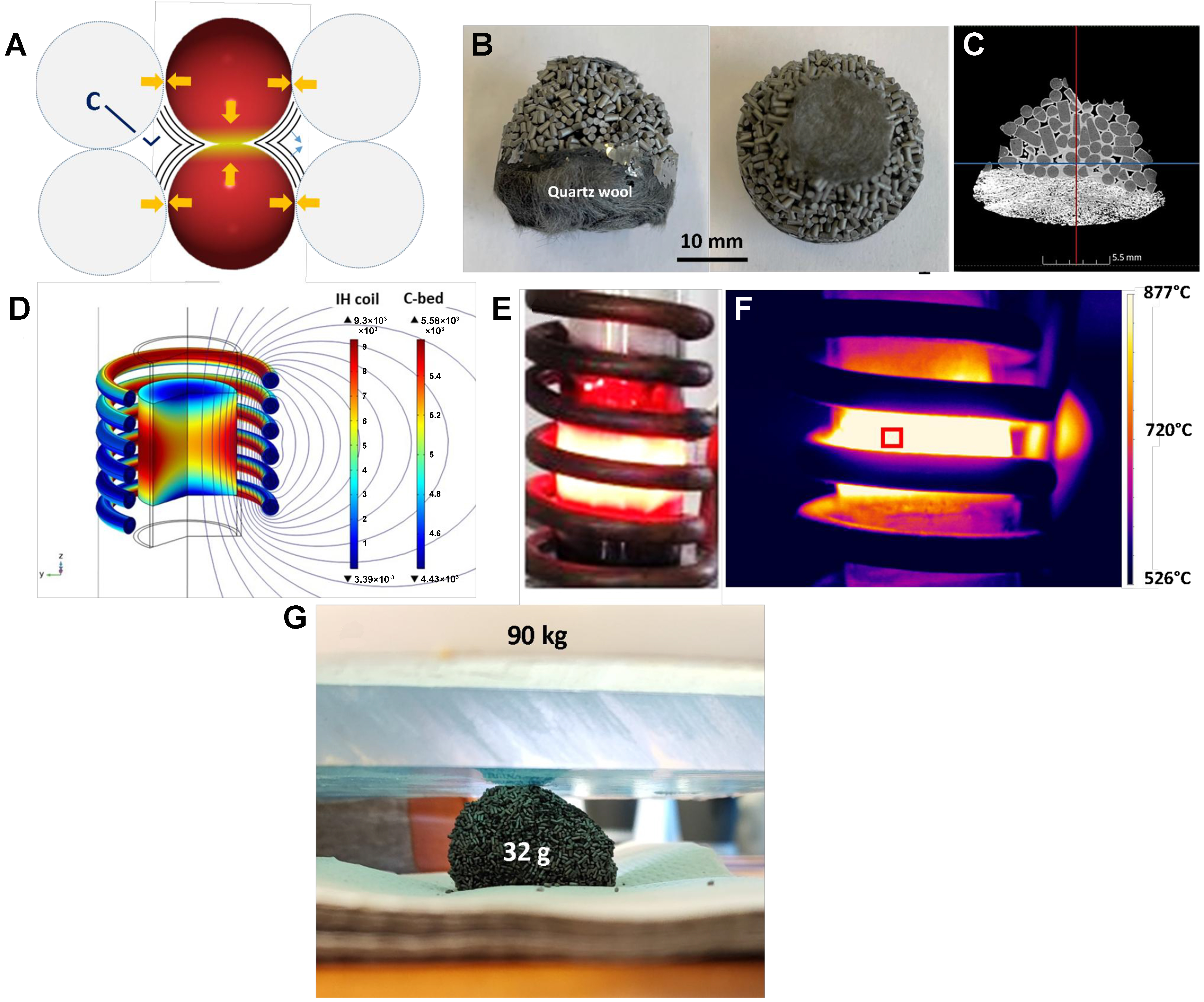
Figure 5. (A) Schematic scheme of the hot spot formation at the contact point between two carbon particles leading to the formation of a continuous graphitic structure between the two particles; (B) Digital photo of the carbon block formed within the reactor after CMD process under IH mode; (C) Cross-section of a TomoX micrograph showing the connection between different MESOC+-1 extrudates through a graphitic-like carbon layer (in bright color); (D) Simulation of the magnetic field concentration in the middle of the induction coil; (E) Digital and (F) thermal photos of the reactor under reaction where a bright zone can be observed in the middle of the induction coil; (G) Digital photo showing the high mechanical resistance of the C-C composite generated during the CMD process with a wt/wt ratio of ca. 2,800 times. CMD: Catalytic decomposition of methane; IH: induction heating.
In IH mode, the temperature gradient of the catalyst between the center of the bed and the edge, near the reactor wall, could also play a role in the localization of carbon deposition. According to the report by Haneishi et al., under the microwave irradiation process, the catalyst temperature in the center of the bed was higher than that near the reactor wall due to heat dissipation at the edge of the catalyst bed[82]. In our case, the reactor was operated without insulation; therefore, heat dissipation is expected to be high near the “cold” wall of the reactor. This gradient temperature is verified by analyzing the spent catalyst: the solid block of the spent catalyst was observed inside and in the middle of the bed where a high regional temperature was expected due to a higher homogeneous magnetic field in the center of the coil and also the local high temperature at the contact points as discussed above [Figure 5D]. On the other parts of the bed, i.e., the upper part located at the entrance, some carbon deposition can be observed, but it was not high enough to connect the different catalyst particles together as that was observed in the middle of the catalyst bed. Such a temperature gradient could also be clearly visualized by digital and thermal photos of Figure 5E and F. This carbon deposit is expected to propagate upwards with TOS to connect the other parts of the catalytic bed to form a macroscopic block. It is worth noting that such a C-C block displays exceptionally high mechanical strength due to the presence of layered graphene-sheet bonding structure. This block
However, the large difference in catalytic performance cannot be attributed solely to the reaction temperature inside the catalyst bed; the presence of an external oscillating magnetic field in the IH may also play a role. Recent works by other research groups suggest that the improvement in catalytic performance under IH, compared to JH, is not only related to heat management but could also be directly influenced by the magnetic field in the catalyst bed. Adogwa et al. have attributed the improvement in catalytic performance under IH to the direct influence of an oscillating magnetic field on the adsorption and desorption rates of the reactant and intermediate species, which enhances the utilization of active sites[83]. These findings remain very similar to those of Kiatphuengporn et al., who linked the improved catalytic performance to the influence of a magnetic field[84]. In the present work, it is expected that the large improvement in catalytic performance of the CMD process, compared to that under indirect JH, may be primarily due to the influence of the magnetic field. Additionally, the presence of this magnetic field could also modify the microstructure and shape of the deposited solid carbon compared to that formed under indirect JH mode.
Influence of the catalyst-specific surface area
According to literature reports, the CMD performance on carbon catalysts, operating under conventional indirect heating, is proportional to the SSA of the catalysts, and progressive deactivation occurs due to the progressive coverage of the carbon catalyst surface by carbon deposition, mainly in amorphous carbon soot form[85-89]. In order to verify this hypothesis, the spent catalyst, obtained under IH mode, with a relatively low SSA of 14 m2/g, was tested again with IH and JH modes. For this cycling test, the spent IH catalyst, denoted as R0, was broken down into small pieces (3 to 5 mm) and re-loaded in the reactor maintaining the same weight (4 g) as that of the fresh catalyst.
In direct IH mode, the methane conversion on the spent R0-IH catalyst increases rapidly to a steady state, even slightly higher compared to that of the fresh catalyst and remains stable for several hours [Figure 6A] while a reverse trend was observed for the same spent R0-IH catalyst operating under indirect JH [Figure 6B]. Indeed, under JH mode, the spent R0-IH catalyst displays much lower methane conversion, indicating that the CMD performance in indirect JH conditions is directly related to the SSA of the catalyst, i.e., 16% methane conversion on MESOC+-1 with 297 m2/g and only 3% on used MESOC+-1 with 14 m2/g. Such results agree well with those reported in the literature where the most active carbon catalysts for CMD required a high SSA[15,23,24,27]; however, this requirement does not appear to apply to the same catalyst when operating in direct IH mode.
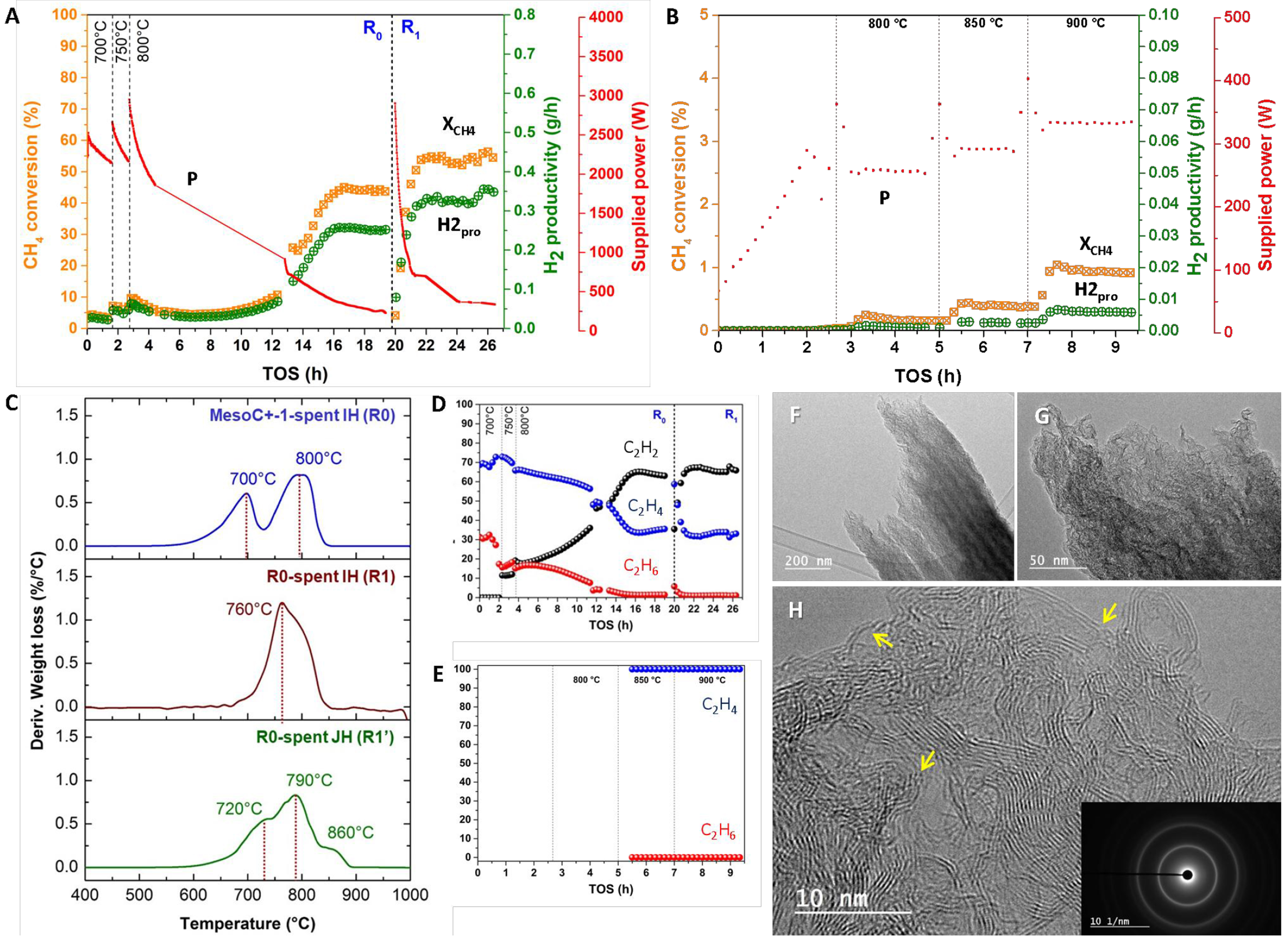
Figure 6. (A) CH4 conversion (XCH4), H2 productivity (H2pro), supplied power (P) on the spent IH (R0) catalyst as a function of temperature and TOS for a second cycling test under direct IH; (B) CH4 conversion (XCH4), H2 productivity (H2pro), supplied power (P) on the same spent IH carbon catalyst as a function of temperature and TOS under indirect JH; (C) TGA spectra of the spent IH catalyst (R0) and the one after a second cycling test under IH (R1) and JH (R1’); (D and E) C2H2, C2H4 and C2H6 distribution as a function of TOS under IH and JH mode, respectively; (F-H) Medium to high-resolution TEM micrographs of the spent IH catalyst after a second cycling test under IH mode showing highly oriented graphene planes with several defects [indicated by arrows in (H)]. IH: Induction heating; TOS: time-on-stream; JH: Joule heating; TGA: thermal gravimetric analysis; TEM: transmission electron microscopy.
The CMD performance of the spent catalyst, operating under direct IH mode, seems to confirm that under non-contact electromagnetic heating, the catalytic activity is not directly related to the SSA of the catalyst, and that the graphene-like layer deposited on the catalyst surface during the reaction could play a catalytic role for the CMD process. The residual amount of virgin R0 carbon contributes only about 39% by weight in the R1 catalyst, although methane conversion remains high in the second cycle test (denoted as R1) which confirms that the CMD performance is directly proportional to the defective surface graphitic deposition material and not to the SSA of the carbon catalyst. The high CMD performance in IH mode could also be due to the presence of a localized heating zone, at the point of contact of the particles, which could generate small regions of high temperature outside equilibrium that contribute to the improvement of the reaction, as discussed above. The influence of the surrounding magnetic field could also play a role despite such influence being not well understood and additional investigation is needed to make a clear assessment.
The TGA spectra of R0 and R1 (spent R0 after IH test) and R1’ (spent R0 after JH test), catalysts after CMD test under IH and JH modes, confirm the higher graphitization behavior of the two spent catalysts [Figure 6C]. The R1’ has the highest TGA temperature peak, i.e., 860 °C, which could be attributed to the high reaction temperature, i.e., 900 °C, for several hours. The C2 fraction on both catalysts exhibits a behavior similar to that obtained on the fresh catalyst which confirms that the reaction is carried out with the same mechanism on both fresh and spent catalysts under these two heating modes [Figure 6D and E]. The microstructure of the graphitic material deposited on the recycled catalyst after IH test (R1) was also studied by TEM. On the recycled catalyst, graphitic is more visible with a high orientation along the growth axis [Figure 6F and G]. A detailed analysis indicates that the graphitic planes remain very defective with the presence of many defects inside the plane, as shown in Figure 6H (indicated by arrows). These defective graphitic sites are expected to act as active sites for the CMD process, as discussed above and in detail in the reaction mechanism proposed below. The defective structure of the carbon deposition is also confirmed by Raman spectroscopy where the D band has a higher contribution than the G band [Figure 3B]. Such a faulty turbostratic structure aligns well with the above TEM analysis where a high density of defects is observed in the carbon plane. It is noteworthy that D bands are associated with the presence of graphitic domain boundary density which is consistent with the SEM analysis.
Influence of cycling tests and temperature
In this section, the spent IH catalyst, after a second cycling test and denoted spent R1, was re-tested for the CMD reaction in IH mode at different temperatures and durations. First, the CMD performance was evaluated at a lower reaction temperature of 780 °C for two consecutive cycling tests, denoted as R2 and R3 [Figure 7A]. The spent R3 catalyst was re-tested as a function of the reaction temperature, and the results again confirm the lack of deactivation on such carbon catalyst [Figure 7B]. After each cycle, the resulting catalyst was broken into small pieces and the same catalyst weight, 4 g, was tested again. For tests R2 and R3, methane conversion increases rapidly to a steady state of about 40%, which is attributed to the low reaction temperature of 780 instead of 800 °C [Figure 7A]. The most striking finding is the high stability of the recycled catalyst, which seems to indicate that deactivation is lacking and that the deposition coke has become increasingly active for the CMD process, i.e., 5% methane conversion at 750 °C on R0 [Figure 2A] against 45% at 780 °C on R2 and R3 [Figure 7A]. Another interesting fact is that as a function of the cycling tests, the SSA of the cycled catalyst continuously decreased from 5 to 1 m2·g-1 for spent R2 and from 1 to
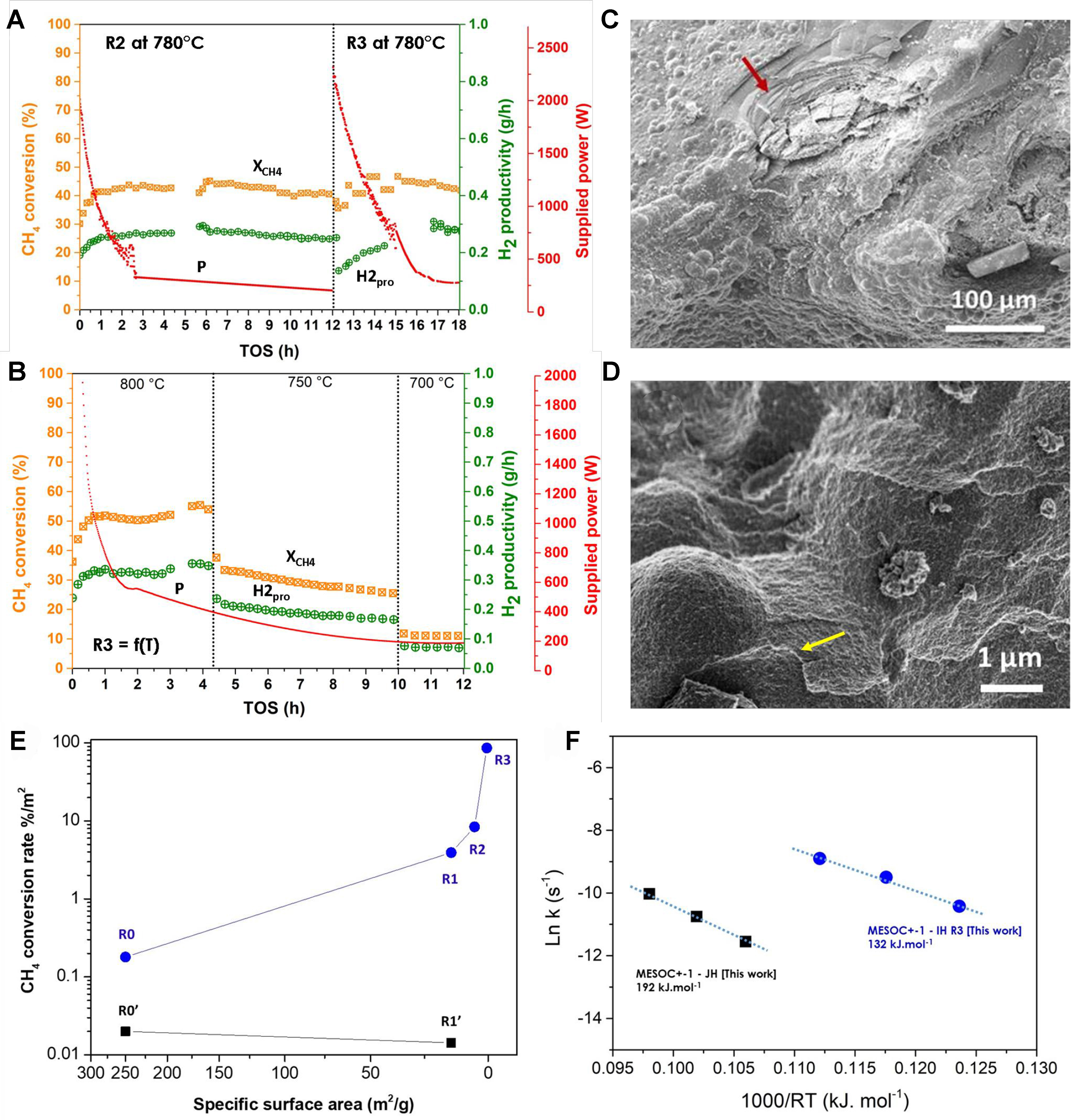
Figure 7. (A) CMD performance [CH4 conversion (XCH4), H2 productivity (H2pro), supplied power (P)] on the spent MESOC+ catalyst after two additional recycling tests (noted R1), at reaction temperature of 780 °C and for two consecutive cycling tests [spent catalyst labeled R2 (third cycling test) and R3 (fourth cycling test)]; (B) CMD performance [CH4 conversion (XCH4), H2 productivity (H2pro), supplied power (P)] on the spent R3 catalyst operated as a function of the reaction temperature ranged from 800 to 700 °C; (C and D) SEM micrographs of the R2 spent catalyst with bubbled carbon microspheres and graphene-like sheets deposited on the surface (indicated by arrows); (E) CMD performance, expressed in terms of CH4converted(%)/m2 (XCH4/m2) with respect to the SSA of the spent catalysts, operated under direct IH (blue) and indirect JH mode (black), showing the reverse relationship between the catalytic performance and the SSA values; (F) Comparison of the activation energy of the R3 catalyst calculated from the catalytic results obtained as a function of the reaction temperature under direct IH, i.e., 700, 750, and 800 °C, and that obtained on the pristine MESOC+ catalyst operated under indirect JH mode. CMD: Catalytic decomposition of methane; SEM: scanning electron microscopy; SSA: specific surface area; IH: induction heating; JH: Joule heating.
The influence of the reaction temperature on the stabilized R3 catalyst was studied: reducing the reaction temperature up to 750 °C seems to induce a slow and continuous decrease in methane conversion, while at 700 °C, an equilibrium state was reached, but at a lower methane conversion [Figure 7B]. The activation energy was calculated from the results obtained on the R3 catalyst and compared to that of the virgin catalyst operating under indirect JH mode [Figure 7F]. It should also be noted that the activation energy of the R3 catalyst is higher than that observed on the first spent IH catalyst (R0), i.e., 132 vs. 86 kJ·mol-1, and could be explained by the sharp reduction in the SSA between the two catalysts, i.e., 0.5 m2·g-1 for the R3 vs. 250 m2·g-1 for the pristine catalyst. However, this activation energy remains lower than that obtained on the spent catalyst after the first test in JH mode, i.e., 132 vs. 192 kJ·mol-1, which confirms again the high efficiency of IH vs. JH mode for operating the CMD process.
Proposed reaction mechanism
A tentative mechanism on carbon formation and its participation in the adsorption and decomposition of methane to produce hydrogen and active solid carbon, based on the morphology analysis of the different spent catalysts as a function of TOS and cycling tests, will be proposed below.
A low-magnification SEM micrograph reveals the presence of micrometric particles decorating the entire surface of the spent R1 catalyst [Figure 8A]. Upon closer inspection, the carbon layer is observed to consist of protruding micrometric particles (with a diameter of about 8 μm) with different flattening shapes. Additionally, smaller nanoparticles are uniformly dispersed on their surface [Figure 8B(i) and (ii)]. A high-magnification SEM micrograph shows that these carbon microspheres are converted into a graphitic sheet stacked on top of each other, which could be attributed to the carbon diffusion from the microsphere to generate a flat carbon surface at the reaction temperature [Figure 8B(i)]. Further examination of a high-resolution SEM micrograph of the carbon hemisphere sitting on top of the catalyst surface [Figure 8B] reveals that this phase is formed from the assembly of many carbon nano-nodules, i.e., about 100 nm
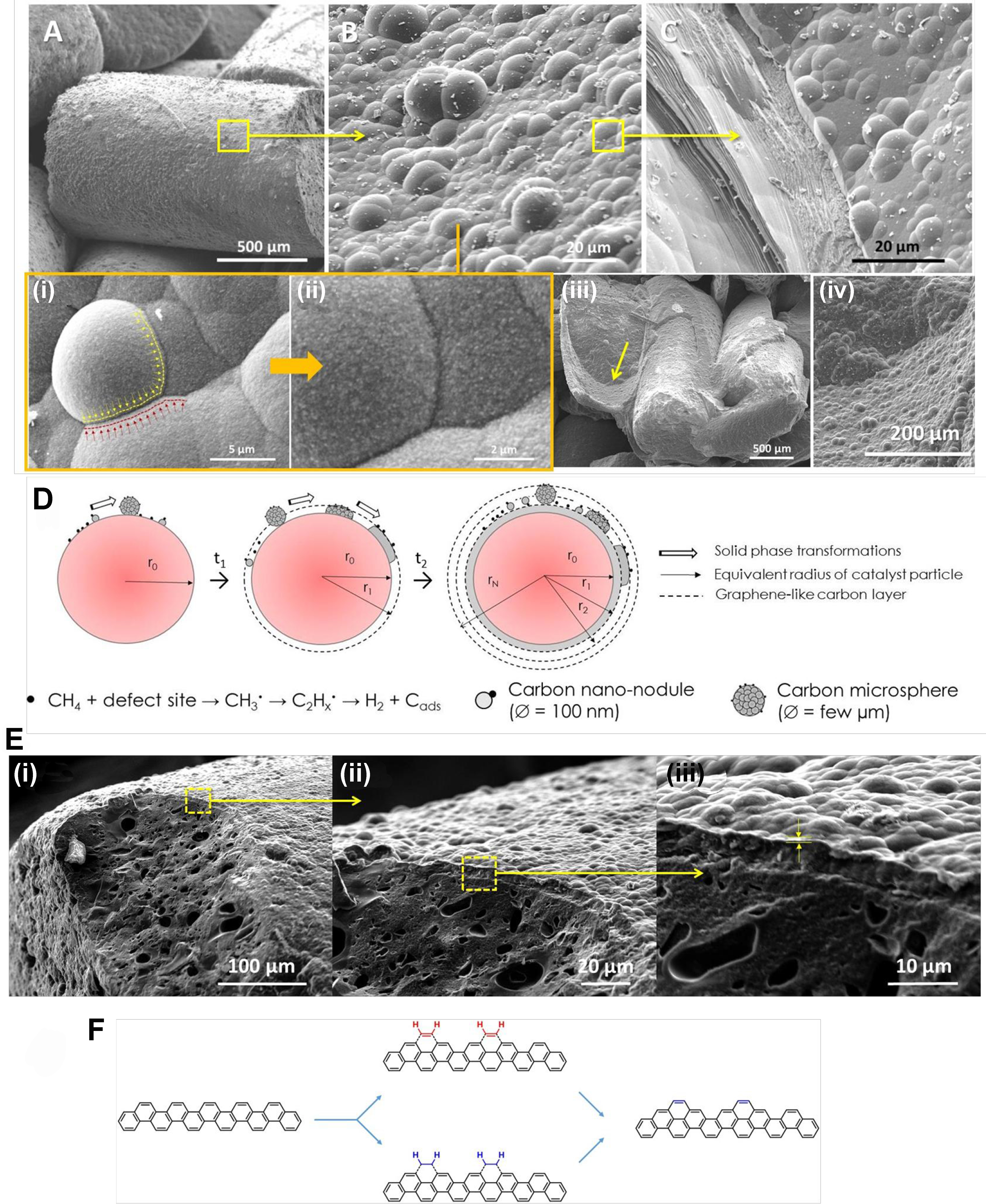
Figure 8. (A-C) SEM micrographs of the spent IH sample (R1) showing the microstructure modification of deposited graphitic compounds: low magnification imaging of deposited graphitic layer, medium resolution imaging of the graphitic nodules and flat graphene sheets structure. [B(i)] Detail imaging of the graphitic nodule flattening. [B(ii)] High-resolution SEM micrograph of the carbon nanoparticles (100 nm) that constitute the graphitic nodules. [B(iii) and (iv)] SEM micrographs showing the inner section of the as-deposited carbon with similar structure as that deposited on the top surface of the spent catalyst; (D) The schematic representation of the growth of the carbon layer by adsorption, coagulation and flattening of gaseous reactants to generate a coating carbon layer; [E(i)-(iii)] SEM micrographs with different magnifications showing the detailed microstructure of the graphene-like layer with bubbling shape deposited on the spent catalyst surface; (F) Schematic representation of the C2H2 incorporation on the armchair according to the CAHA mechanism. SEM: Scanning electron microscopy; IH: induction heating; CAHA: hydrogen extraction addition (or adsorption) mechanism.
The SEM analysis was again performed on the recycled R1 catalyst (denoted as R2) and the same growth mechanism, i.e., carbon nano-nodules → carbon microparticles → merging and flattening processes to generate graphene-like structure [Figure 8C] leading to structural collapse to generate a bubbling carbon layer, was observed again on the surface of the recycled catalyst and the exposed inner surface of the sample R0 [Figure 8B(iii) and (iv)]. Such a “fractal” growth mechanism helps explain the maintenance of the CMD catalytic performance of the spent catalyst, because each freshly exposed carbon surface represents a new surface for carbon deposition, regardless of the origin of the “fresh” exposed carbon surface, whether virgin or spent catalysts. The new exposed surface is quickly covered with carbon microspheres similar to what is observed on the virgin R0 catalyst. The flattening of the bubbling morphology into a layered morphology could be explained by the loosening of the carbon structure in the layer by the surface diffusion process in order to reduce surface energy. This relaxation process should be facilitated by the relatively high reaction temperature of the process, i.e.,
According to data reported by Lee et al., the defect sites located on the graphene-like edges could act as active sites to adsorb acetylene on the carbon chair to generate a new carbon structure with a concomitant release of hydrogen providing an autocatalytic process (see schematic representation of the addition process in Figure 8F)[91]. Such a reaction also depends on the reaction temperature, and at 500 °C and below, the hydrogen atoms contained in the chemisorbed C2Hx cannot be extracted and, therefore, prevent subsequent chemisorption of C2Hx on previously chemisorbed species[92]. At a temperature ≥ 600 °C, the hydrogen atoms of the C2H2 (or C2H4) chemisorbed species can be easily extracted, leading to the formation of a new carbon ring on the face of the chair that could again act as a host site for the chemisorption of other molecules to trigger the CMD reaction. This process is called the “hydrogen extraction addition (or adsorption) mechanism (CAHA) in C2H2” according to the reports of Frenklach et al.[93]. It has been reported that defects present on the edges of graphene could be the active sites for the execution of the CMD process by the CAHA mechanism[94].
The direct involvement of C2H2 in the insertion of carbon on the defective turbostratic defect could thus be put forward to explain our results. However, at the elevated reaction temperature of 800 °C, it is expected that a large amount of C2H2 has formed and that some of the C2H2 has not been adsorbed and converted to carbonaceous species, probably due to the saturation of the defective sites, and, thus, the leakage in the output stream. For all catalysts tested, a significant amount of C2H2 was detected in the output stream, which could indicate that the spent catalyst produces more C2H2 compared to the fresh catalyst and, therefore, some of the C2H2 exits the catalytic bed without being converted. Such non-oxidative coupling of methane on the carbon catalyst could be explained by the influence of the electromagnetic field, generated by induction, which could induce the formation and combination of radicals according to some recent reports[72].
The observed results clearly indicate that the graphene-like carbon structure generated during the CMD process is responsible for the CMD catalytic performance by the layer-by-layer accumulation of turbostratic with highly defective edge planes acting as adsorption sites for the methane decomposition process. The formation of such a basal plane also contributes to the directional improvement of the thermal conductivity of the sample by improving the conduction of phonons and electrons along the basal planes (direction a) than by the stacked plane (direction c) of the anisotropic pyrolytic carbon layers. The combination of the greater amount of carbon deposited inside the induction coil, the interconnection of the different carbon extrudates from each other and the improvement in thermal conductivity significantly reduces the overall power input for system operation, as observed in our results. In addition, the carbon deposit occurred in the presence of hydrogen atmosphere at a relatively high temperature which could also facilitate some direct hydrogen titration of the carbon site. Carbon in graphene plane that is bonded with hydrogen shifts to a different configuration which then becomes active under a magnetic field[95]. It could be thus argued that during this process, part of the carbon formed is bonded with hydrogen to generate a graphane structure which can be activated by the presence of a magnetic field and participate in the adsorption of methane or acetylene to push up the CMD reaction. Additionally, the presence of adatoms, defects or zig-zag structure inside the graphene plane could also induce magnetism within the material[96-98].
CONCLUSION
In summary, CMD can be efficiently performed on metal-free carbon-based carbon, i.e., industrial carbon MESOC+, under contactless IH at a reaction temperature of 800 ± 100 °C. The results obtained from different cycling tests clearly demonstrated that the defective graphitic material deposited during the process can act as a new metal-free active phase for the realization of CMD leading to an autocatalytic process. On the other hand, the same catalyst operating under indirect JH showed a similar catalytic tendency to that reported in the literature where a low CMD performance was obtained at a reaction temperature ≤ 1,000 °C alongside deactivation. The CMD performance under indirect JH was also significantly influenced by the SSA of the catalyst, while for direct IH, no such relationship was observed, which also highlighted a different catalytic activity. It is expected that defects in the graphitic edge plane of the deposited carbon can act as anchor sites for the reaction intermediate, acetylene, to produce a new layer of carbon and hydrogen.
The high and stable CMD catalytic performance obtained on the MESOC+ catalyst under IH was attributed to the efficient temperature regulation thanks to the high and targeted heating properties of the inductor. In addition, this catalytic performance could also be due to the presence of an oscillating magnetic field inside the catalyst bed which could induce modification on the adsorption and desorption rates of the reactant and the intermediates according to recent reports. The magnetic field could also influence the formation of a solid carbon with graphene-like layered structure compared to carbon nodules formed under the contactless JH.
Such a discovery opens a new avenue for the industrial development of CMD on carbon-based catalysts with significant cost-effectiveness and a process with low environmental impact where the carbon formed from the process can be directly re-used as an active phase. In such a process, no additional need for periodic regeneration is required, as they are usually encountered with existing processes, which also significantly reduces the complexity of the process and its operational environment and operating cost. It is worth noting that although carbon-based catalysts required a higher operating temperature than metal-based catalysts, the use of carbon-based catalysts results in the formation of a carbon composite, which can be directly used in many applications without any post-processing steps, which contributes to the reduction of the overall cost of the process. Such a hydrogen production process could be expected to be industrially viable and possibly competitive with the SMR process coupled with CO2 capture and storage (from process and flue gases). In addition, when using biomethane as a source of hydrogen, the CMD process makes it possible to produce hydrogen from renewable sources and convert the carbon contained in the former biomass back into solid carbon that can be used as a soil amendment or in other processes. Work is underway to further elucidate the reaction mechanism operated under induction electromagnetic heating regarding future optimization of the process.
DECLARATIONS
Acknowledgments
The authors would like to thank TotalEnergies for financially supporting the work presented in this article. The carbon sample was provided by SICAT SAS and Dr. C. Pham is gratefully acknowledged for technical discussions. The authors have no affiliation with SICAT SAS. The TEM analysis was performed at the TEM platform of IS2M (UMR 7361), SEM analysis at the SEM-Cronenbourg platform facilities (ICPEES, UMR 7515), and TomoX analysis at the TomoX platform of the ICS (UPR 22). A. Egele and D. Favier are gratefully acknowledged for their contributions to the experiments and technical discussions. Dr. M. Dumont (EMDPI) is also thanked for his technical discussion and assistance throughout the project.
Authors’ contributions
Methodology, data acquisition, experiments, writing: Truong-Phuoc L
Methodology, data acquisition, experiments: Essyed A, Pham HX
Data acquisition: Romero T
Experimental discussion, financing, supervision, writing: Dath JP, Pham-Huu C
Experimental discussion, experiments, formal analysis: Nhut JM
Experimental discussion, formal analysis, supervision, writing: Brazier A
Data acquisition, experimental discussion: Vidal L
Experimental discussion, data acquisition, formal analysis: Nguyen-Dinh L
Availability of data and materials
A detailed description of the characterization techniques and characterization of the different products by GC techniques are presented in the Supplementary Materials, and the data supporting the findings of this study are available within its Supplementary Materials.
Financial support and sponsorship
This work was supported by the R&D project between TotalEnergies and ICPEES (Contract No. 291508 _HYDRA).
Conflicts of interest
The article is based on the results obtained at ICPEES through collaboration between ICPEES and TotalEnergies. Dath JP and Brazier A are affiliated with TotalEnergies, while the other authors have declared that they have no conflicts of interest.
Ethical approval and consent to participate
Not applicable.
Consent for publication
Not applicable.
Copyright
© The Author(s) 2024.
Supplementary Materials
REFERENCES
1. Ishaq H, Dincer I, Crawford C. A review on hydrogen production and utilization: challenges and opportunities. Int J Hydrogen Energ. 2022;47:26238-64.
2. Megía PJ, Vizcaíno AJ, Calles JA, Carrero A. Hydrogen production technologies: from fossil fuels toward renewable sources. a mini review. Energy Fuels. 2021;35:16403-15.
3. Nikolaidis P, Poullikkas A. A comparative overview of hydrogen production processes. Renew Sust Energ Rev. 2017;67:597-611.
4. Massarweh O, Al-khuzaei M, Al-shafi M, Bicer Y, Abushaikha AS. Blue hydrogen production from natural gas reservoirs: a review of application and feasibility. J CO2 Util. 2023;70:102438.
5. Wismann ST, Engbæk JS, Vendelbo SB, et al. Electrified methane reforming: a compact approach to greener industrial hydrogen production. Science. 2019;364:756-9.
6. Spath PL, Mann MK. Life cycle assessment of hydrogen production via natural gas steam reforming. Available from: https://www.nrel.gov/docs/fy01osti/27637.pdf. [Last accessed on 26 Aug 2024].
7. Kumar A, Baldea M, Edgar TF. A physics-based model for industrial steam-methane reformer optimization with non-uniform temperature field. Comput Chem Eng. 2017;105:224-36.
8. Wismann ST, Engbæk JS, Vendelbo SB, et al. Electrified methane reforming: elucidating transient phenomena. Chem Eng J. 2021;425:131509.
9. Ambrosetti M, Beretta A, Groppi G, Tronconi E. A numerical investigation of electrically-heated methane steam reforming over structured catalysts. Front Chem Eng. 2021;3:747636.
10. Alves L, Pereira V, Lagarteira T, Mendes A. Catalytic methane decomposition to boost the energy transition: scientific and technological advancements. Renew Sust Energ Rev. 2021;137:110465.
11. Fan Z, Weng W, Zhou J, Gu D, Xiao W. Catalytic decomposition of methane to produce hydrogen: a review. J Energy Chem. 2021;58:415-30.
12. Schneider S, Bajohr S, Graf F, Kolb T. State of the art of hydrogen production via pyrolysis of natural gas. Chem Ing Tech. 2020;92:1023-32.
13. Dincer I, Acar C. Review and evaluation of hydrogen production methods for better sustainability. Int J Hydrogen Energ. 2015;40:11094-111.
14. Tong S, Miao B, Chan SH. A numerical study on turquoise hydrogen production by catalytic decomposition of methane. Chem Eng Process. 2023;186:109323.
15. Hermesmann M, Müller T. Green, turquoise, blue, or grey? Environmentally friendly hydrogen production in transforming energy systems. Prog Energ Combust. 2022;90:100996.
16. Gautier M, Rohani V, Fulcheri L, Trelles JP. Influence of temperature and pressure on carbon black size distribution during allothermal cracking of methane. Aerosol Sci Tech. 2016;50:26-40.
17. Lebarbier VM, Dagle RA, Kovarik L, et al. Sorption-enhanced synthetic natural gas (SNG) production from syngas: a novel process combining CO methanation, water-gas shift, and CO2 capture. Appl Catal B Environ. 2014;144:223-32.
19. Abbas HF, Wan Daud W. Hydrogen production by methane decomposition: a review. Int J Hydrogen Energ. 2010;35:1160-90.
20. Wang G, Jin Y, Liu G, Li Y. Production of hydrogen and nanocarbon from catalytic decomposition of methane over a Ni-Fe/Al2O3 catalyst. Energy Fuels. 2013;27:4448-56.
21. Torres D, de Llobet S, Pinilla J, Lázaro M, Suelves I, Moliner R. Hydrogen production by catalytic decomposition of methane using a Fe-based catalyst in a fluidized bed reactor. J Nat Gas Chem. 2012;21:367-73.
22. Kreuger T, van Swaaij W, Kersten S. Methane pyrolysis over porous particles. Catal Today. 2023;420:114058.
23. Luo H, Qiao Y, Ning Z, Bo C, Hu J. Effect of thermal extraction on coal-based activated carbon for methane decomposition to hydrogen. ACS Omega. 2020;5:2465-72.
24. Ashik U, Wan Daud W, Abbas HF. Production of greenhouse gas free hydrogen by thermocatalytic decomposition of methane - a review. Renew Sust Energ Rev. 2015;44:221-56.
25. Zhang J, Li X, Chen H, et al. Hydrogen production by catalytic methane decomposition: carbon materials as catalysts or catalyst supports. Int J Hydrogen Energ. 2017;42:19755-75.
26. Li Y, Li D, Wang G. Methane decomposition to COx-free hydrogen and nano-carbon material on group 8-10 base metal catalysts: a review. Catal Today. 2011;162:1-48.
27. Gulino G, Vieira R, Amadou J, et al. C2H6 as an active carbon source for a large scale synthesis of carbon nanotubes by chemical vapour deposition. Appl Catal A Gen. 2005;279:89-97.
28. Pinilla J, Suelves I, Lázaro M, Moliner R. Influence on hydrogen production of the minor components of natural gas during its decomposition using carbonaceous catalysts. J Power Sources. 2009;192:100-6.
29. Fidalgo B, Muradov N, Menéndez J. Effect of H2S on carbon-catalyzed methane decomposition and CO2 reforming reactions. Int J Hydrogen Energ. 2012;37:14187-94.
30. Lucia O, Maussion P, Dede EJ, Burdio JM. Induction heating technology and its applications: past developments, current technology, and future challenges. IEEE Trans Ind Electron. 2014;61:2509-20.
31. Kuhwald C, Türkhan S, Kirschning A. Inductive heating and flow chemistry - a perfect synergy of emerging enabling technologies. Beilstein J Org Chem. 2022;18:688-706.
32. Chatterjee S, Houlding TK, Doluda VY, Molchanov VP, Matveeva VG, Rebrov EV. Thermal behavior of a catalytic packed-bed milli-reactor operated under radio frequency heating. Ind Eng Chem Res. 2017;56:13273-80.
33. Faure S, Kale SS, Mille N, et al. Improving energy efficiency of magnetic CO2 methanation by modifying coil design, heating agents, and by using eddy currents as the complementary heating source. J Appl Phys. 2021;129:044901.
34. Whajah B, da Silva Moura N, Blanchard J, et al. Catalytic depolymerization of waste polyolefins by induction heating: selective alkane/alkene production. Ind Eng Chem Res. 2021;60:15141-50.
35. Piner R, Li H, Kong X, et al. Graphene synthesis via magnetic inductive heating of copper substrates. ACS Nano. 2013;7:7495-9.
36. Ramirez A, Hueso JL, Abian M, Alzueta MU, Mallada R, Santamaria J. Escaping undesired gas-phase chemistry: microwave-driven selectivity enhancement in heterogeneous catalytic reactors. Sci Adv. 2019;5:eaau9000.
37. Marbaix J, Mille N, Lacroix L, et al. Tuning the composition of FeCo nanoparticle heating agents for magnetically induced catalysis. ACS Appl Nano Mater. 2020;3:3767-78.
38. Kreissl H, Jin J, Lin SH, et al. Commercial Cu2Cr2O5 decorated with iron carbide nanoparticles as a multifunctional catalyst for magnetically induced continuous-flow hydrogenation of aromatic ketones. Angew Chem Int Ed Engl 2021;60:26639-46.
39. Cerezo-Navarrete C, Marin IM, García-Miquel H, Corma A, Chaudret B, Martínez-Prieto LM. Magnetically induced catalytic reduction of biomass-derived oxygenated compounds in water. ACS Catal. 2022;12:8462-75.
40. Mustieles Marin I, De Masi D, Lacroix L, et al. Hydrodeoxygenation and hydrogenolysis of biomass-based materials using FeNi catalysts and magnetic induction. Green Chem. 2021;23:2025-36.
41. Truong-phuoc L, Duong-viet C, Tuci G, et al. Graphite felt-sandwiched Ni/SiC catalysts for the induction versus joule-heated sabatier reaction: assessing the catalyst temperature at the nanoscale. ACS Sustain Chem Eng. 2022;10:622-32.
42. Niether C, Faure S, Bordet A, et al. Improved water electrolysis using magnetic heating of FeC–Ni core–shell nanoparticles. Nat Energy. 2018;3:476-83.
43. Lin S, Hetaba W, Chaudret B, Leitner W, Bordet A. Copper-decorated iron carbide nanoparticles heated by magnetic induction as adaptive multifunctional catalysts for the selective hydrodeoxygenation of aldehydes (Adv. Energy Mater. 42/2022). Adv Energy Mater. 2022;12:2270173.
44. Vinum MG, Almind MR, Engbæk JS, et al. Dual-function cobalt–nickel nanoparticles tailored for high-temperature induction-heated steam methane reforming. Angew Chem. 2018;130:10729-33.
45. Mortensen PM, Engbæk JS, Vendelbo SB, Hansen MF, Østberg M. Direct hysteresis heating of catalytically active Ni–Co nanoparticles as steam reforming catalyst. Ind Eng Chem Res. 2017;56:14006-13.
46. Nguyen HM, Phan CM, Liu S, Pham-huu C, Nguyen-dinh L. Radio-frequency induction heating powered low-temperature catalytic CO2 conversion via bi-reforming of methane. Chem Eng J. 2022;430:132934.
47. Truong-huu T, Duong-viet C, Duong-the H, et al. Radiofrequency-driven selective oxidation of H2S on hierarchical metal-free catalyst containing defects. Appl Catal A Gen. 2021;620:118171.
48. Wang W, Duong-viet C, Truong-phuoc L, Nhut J, Vidal L, Pham-huu C. Activated carbon supported nickel catalyst for selective CO2 hydrogenation to synthetic methane under contactless induction heating. Catal Today. 2023;418:114073.
49. Ramirez A, Hueso JL, Mallada R, Santamaria J. Microwave-activated structured reactors to maximize propylene selectivity in the oxidative dehydrogenation of propane. Chem Eng J. 2020;393:124746.
50. Fulcheri L, Rohani V, Wyse E, Hardman N, Dames E. An energy-efficient plasma methane pyrolysis process for high yields of carbon black and hydrogen. Int J Hydrogen Energ. 2023;48:2920-8.
51. Wang W, Tuci G, Duong-viet C, et al. Induction heating: an enabling technology for the heat management in catalytic processes. ACS Catal. 2019;9:7921-35.
52. Bursavich J, Abu-laban M, Muley PD, Boldor D, Hayes DJ. Thermal performance and surface analysis of steel-supported platinum nanoparticles designed for bio-oil catalytic upconversion during radio frequency-based inductive heating. Energ Convers Manage. 2019;183:689-97.
53. Wang W, Duong-Viet C, Tuci G, et al. Highly nickel-loaded γ-alumina composites for a radiofrequency-heated, low-temperature CO2 methanation scheme. ChemSusChem. 2020;13:5468-79.
54. Schiffer ZJ, Manthiram K. Electrification and decarbonization of the chemical industry. Joule. 2017;1:10-4.
55. Francke L, Benquet C, Dath JP, Truong-Phuoc L, Pham-Huu C, Nhut JM. 1. WO2023073000 - Process for the production of hydrogen and carbon by catalytic non-oxidative decomposition of hydrocarbons. Available from: https://patentscope.wipo.int/search/zh/detail.jsf?docId=WO2023073000&recNum=1&maxRec=1&office=&prevFilter=&sortOption=&queryString=&tab=PCT+Biblio. [Last accessed on 26 Aug 2024]
56. Wang W, Duong-viet C, Truong-phuoc L, et al. Improving catalytic performance via induction heating: selective oxidation of H2S on a nitrogen-doped carbon catalyst as a model reaction. New J Chem. 2023;47:1105-16.
57. Wehinger GD. Improving the radial heat transport and heat distribution in catalytic gas-solid reactors. Chem Eng Process. 2022;177:108996.
58. Duong-viet C, Truong-phuoc L, Nguyen-dinh L, et al. Magnetic induction assisted pyrolysis of plastic waste to liquid hydrocarbons on carbon catalyst. Mater Today Catal. 2023;3:100028.
59. Mantiply ED, Pohl KR, Poppel SW, Murphy JA. Summary of measured radiofrequency electric and magnetic fields (10 kHz to 30 GHz) in the general and work environment. Bioelectromagnetics. 1997;18:563-77.
60. Al-hassani AA, Abbas HF, Wan Daud W. Hydrogen production via decomposition of methane over activated carbons as catalysts: full factorial design. Int J Hydrogen Energ. 2014;39:7004-14.
61. Pinilla J, Suelves I, Lázaro M, Moliner R. Kinetic study of the thermal decomposition of methane using carbonaceous catalysts. Chem Eng J. 2008;138:301-6.
62. Nishii H, Miyamoto D, Umeda Y, et al. Catalytic activity of several carbons with different structures for methane decomposition and by-produced carbons. Appl Surf Sci. 2019;473:291-7.
63. Ba H, Tuci G, Evangelisti C, et al. Second youth of a metal-free dehydrogenation catalyst: when γ-Al2O3 meets coke under oxygen- and steam-free conditions. ACS Catal. 2019;9:9474-84.
64. Ba H, Truong-phuoc L, Liu Y, et al. Hierarchical carbon nanofibers/graphene composite containing nanodiamonds for direct dehydrogenation of ethylbenzene. Carbon. 2016;96:1060-9.
65. Li S, Gu Q, Cao N, et al. Defect enriched N-doped carbon nanoflakes as robust carbocatalysts for H2S selective oxidation. J Mater Chem A. 2020;8:8892-902.
66. Osipov AR, Sidorchik IA, Shlyapin DA, Borisov VA, Leontieva NN, Lavrenov AV. Thermocatalytic decomposition of methane on carbon materials and its application in hydrogen production technologies. Kat v prom. 2021;1:47-54.
67. Malhotra A, Chen W, Goyal H, et al. Temperature homogeneity under selective and localized microwave heating in structured flow reactors. Ind Eng Chem Res. 2021;60:6835-47.
68. Hsieh LT, Lee WJ, Chen CY, Chang MB, Chang HC. Converting methane by using an RF plasma reactor. Plasma Chem Plasma P. 1998;18:215-39.
69. Kosinov N, Hensen EJM. Reactivity, selectivity, and stability of zeolite-based catalysts for methane dehydroaromatization. Adv Mater. 2020;32:e2002565.
70. Beuque A, Hao H, Berrier E, et al. How do the products in methane dehydroaromatization impact the distinct stages of the reaction? Appl Catal B Environ. 2022;309:121274.
71. Ikeya N, Woodward JR. Cellular autofluorescence is magnetic field sensitive. Proc Natl Acad Sci U S A. 2021;118:e2018043118.
72. Liu D, Huang Y, Hu J, Wang B, Lu Y. Multiscale catalysis under magnetic fields: methodologies, advances, and trends. ChemCatChem. 2022;14:e202200889.
73. Harmon NJ, Flatté ME. Distinguishing spin relaxation mechanisms in organic semiconductors. Phys Rev Lett. 2013;110:176602.
74. Li X, Wang W, Dong F, et al. Recent advances in noncontact external-field-assisted photocatalysis: from fundamentals to applications. ACS Catal. 2021;11:4739-69.
76. Osswald S, Havel M, Gogotsi Y. Monitoring oxidation of multiwalled carbon nanotubes by Raman spectroscopy. J Raman Spectroscopy. 2007;38:728-36.
77. Julian I, Ramirez H, Hueso JL, Mallada R, Santamaria J. Non-oxidative methane conversion in microwave-assisted structured reactors. Chem Eng J. 2019;377:119764.
78. Tuci G, Liu Y, Rossin A, et al. Porous silicon carbide (SiC): a chance for improving catalysts or just another active-phase carrier? Chem Rev. 2021;121:10559-665.
79. Pham-huu C, Ledoux M. Carbon nanomaterials with controlled macroscopic shapes as new catalytic materials. Top Catal. 2006;40:49-63.
80. Haneishi N, Tsubaki S, Abe E, et al. Enhancement of fixed-bed flow reactions under microwave irradiation by local heating at the vicinal contact points of catalyst particles. Sci Rep. 2019;9:222.
81. Khattak HK, Bianucci P, Slepkov AD. Linking plasma formation in grapes to microwave resonances of aqueous dimers. Proc Natl Acad Sci U S A. 2019;116:4000-5.
82. Haneishi N, Tsubaki S, Maitani MM, Suzuki E, Fujii S, Wada Y. Electromagnetic and heat-transfer simulation of the catalytic dehydrogenation of ethylbenzene under microwave irradiation. Ind Eng Chem Res. 2017;56:7685-92.
83. Adogwa A, Chukwu E, Malaj A, et al. Catalytic reaction triggered by magnetic induction heating mechanistically distinguishes itself from the standard thermal reaction. ACS Catal. 2024;14:4008-17.
84. Kiatphuengporn S, Jantaratana P, Limtrakul J, Chareonpanich M. Magnetic field-enhanced catalytic CO2 hydrogenation and selective conversion to light hydrocarbons over Fe/MCM-41 catalysts. Chem Eng J. 2016;306:866-75.
85. Moliner R, Suelves I, Lazaro M, Moreno O. Thermocatalytic decomposition of methane over activated carbons: influence of textural properties and surface chemistry. Int J Hydrogen Energ. 2005;30:293-300.
86. Lee EK, Lee SY, Han GY, et al. Catalytic decomposition of methane over carbon blacks for CO2-free hydrogen production. Carbon. 2004;42:2641-8.
87. Kim MH, Lee EK, Jun JH, et al. Hydrogen production by catalytic decomposition of methane over activated carbons: kinetic study. Int J Hydrogen Energ. 2004;29:187-93.
88. Krzyzynski S, Kozlowski M. Activated carbons as catalysts for hydrogen production via methane decomposition. Int J Hydrogen Energ. 2008;33:6172-7.
89. Ashok J, Kumar SN, Venugopal A, Kumari VD, Tripathi S, Subrahmanyam M. COx free hydrogen by methane decomposition over activated carbons. Catal Commun. 2008;9:164-9.
90. Xavier NF Jr, Bauerfeldt GF, Sacchi M. First-principles microkinetic modeling unravelling the performance of edge-decorated nanocarbons for hydrogen production from methane. ACS Appl Mater Interfaces. 2023;15:6951-62.
91. Lee SY, Kwak JH, Han GY, Lee TJ, Yoon KJ. Characterization of active sites for methane decomposition on carbon black through acetylene chemisorption. Carbon. 2008;46:342-8.
92. Moriarty NW, Brown NJ, Frenklach M. Hydrogen migration in the phenylethen-2-yl radical. J Phys Chem A. 1999;103:7127-35.
93. Frenklach M, Ping J. On the role of surface migration in the growth and structure of graphene layers. Carbon. 2004;42:1209-12.
94. Tokunaga T, Kishi N, Yamakawa K, Sasaki K, Yamamoto T. Methane decomposition for hydrogen production by catalytic activity of carbon black under low flow rate conditions. J Ceram Soc Japan. 2017;125:185-9.
95. Thakur B, Chandra Shekar N, Chandra S, Chakravarty S. Effect of sp hybridization and bond-length disorder on magnetism in amorphous carbon - a first-principles study. Diamond and Related Materials. 2022;121:108725.
97. Gao Y, Feng X, Gong B, et al. Theoretical design of all-carbon networks with intrinsic magnetism. Carbon. 2021;177:11-8.
Cite This Article
How to Cite
Download Citation
Export Citation File:
Type of Import
Tips on Downloading Citation
Citation Manager File Format
Type of Import
Direct Import: When the Direct Import option is selected (the default state), a dialogue box will give you the option to Save or Open the downloaded citation data. Choosing Open will either launch your citation manager or give you a choice of applications with which to use the metadata. The Save option saves the file locally for later use.
Indirect Import: When the Indirect Import option is selected, the metadata is displayed and may be copied and pasted as needed.
About This Article
Special Topic
Copyright


Comments
Comments must be written in English. Spam, offensive content, impersonation, and private information will not be permitted. If any comment is reported and identified as inappropriate content by OAE staff, the comment will be removed without notice. If you have any queries or need any help, please contact us at support@oaepublish.com.